











Product Details
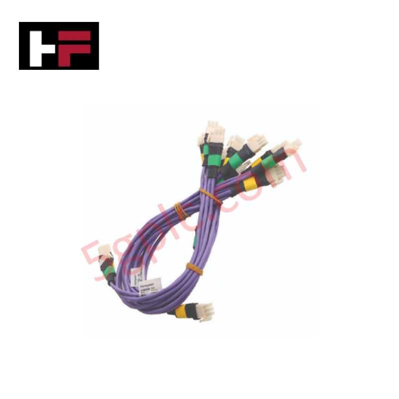
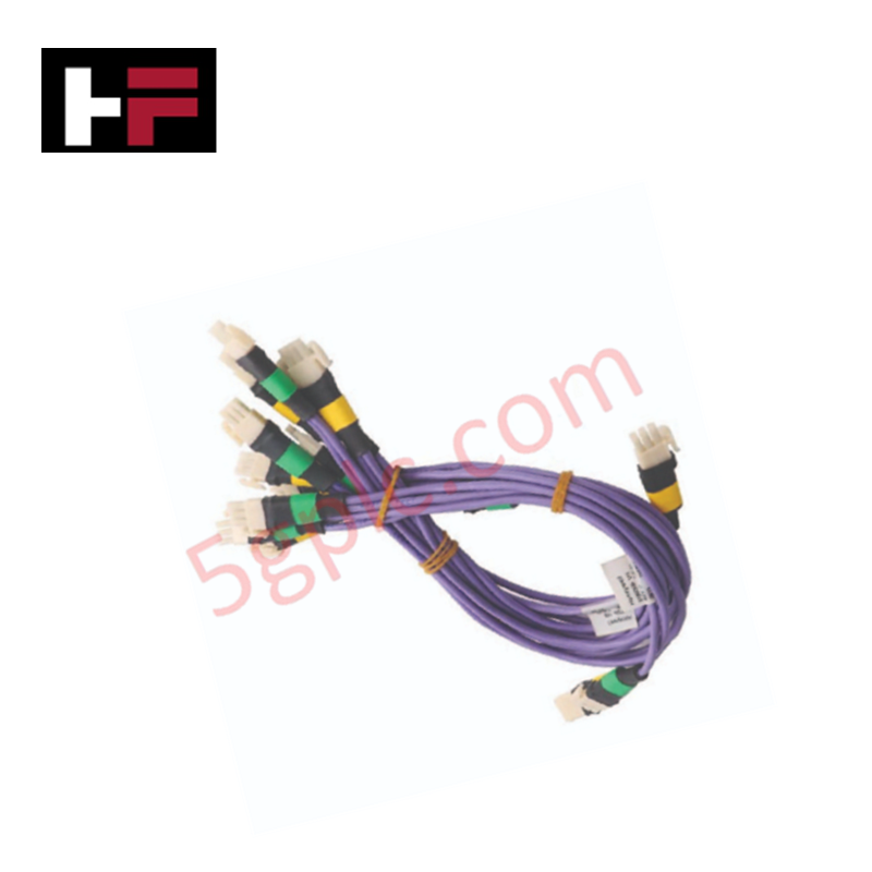
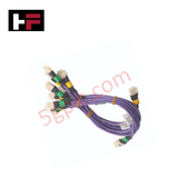
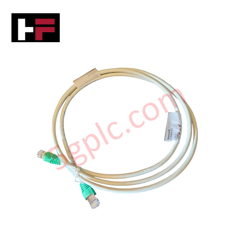
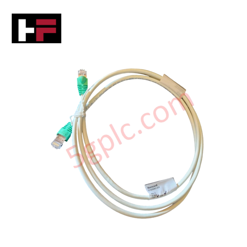
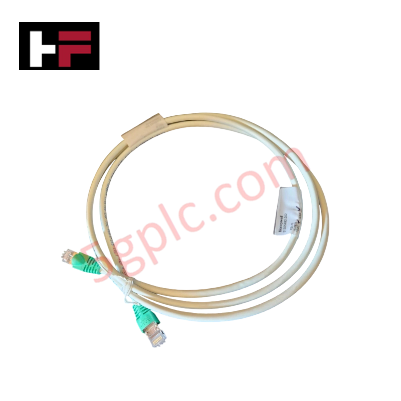
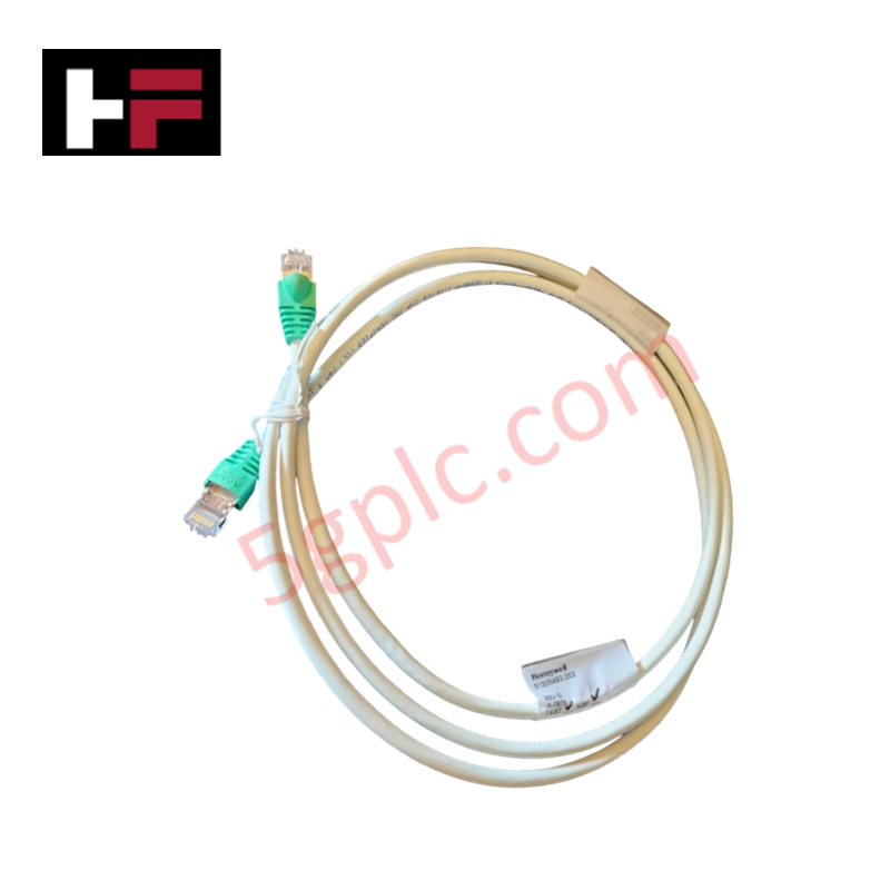
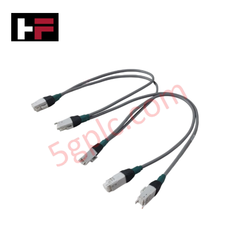
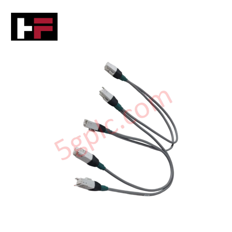
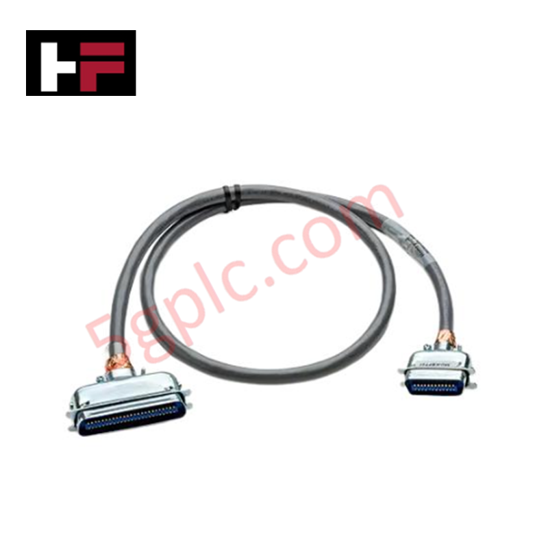
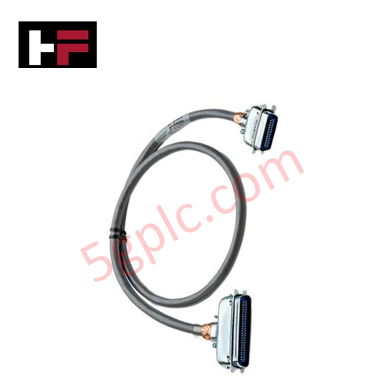
The Honeywell 41202329-401, also cataloged as the 41202329 I/O Link Cable, operates as a dedicated hardware component for signal transmission and shielded interconnection within Honeywell DCS networks.
Hardware Specifications
| Parameter | Specification |
|---|---|
| Model | 41202329-401 |
| Brand | Honeywell |
| Origin | USA |
| Operating Temp | -20 to +70 deg C |
| Power Consumption | Passive interconnect assembly |
| Cable Type | I/O link cable |
| Voltage Rating | Low-voltage signal class |
| Shielding | Integrated EMI/RFI-shielded braid |
| Connector Type | Honeywell-specific factory-terminated connectors |
4-20 mA HART Loop & Channel-to-Channel Isolation Characteristics
Engineered with high-density shielding braid and multi-conductor geometry, the cable preserves channel-to-channel isolation across multi-drop card configurations. This structural insulation prevents capacitive cross-talk and electromagnetic noise coupling between adjacent analog and 4-20 mA HART loop signal paths. In multi-module DCS environments, maintaining pure signal integrity prevents noise overlay onto primary process variables and diagnostic data packets.
Frequently Asked Questions
Q: Can the 41202329-401 cable be disconnected while the system is powered and operational?
A: Physical disconnection is safe for the passive cable, but causes immediate transient signal loss on the active link; controlled channel isolation or loop de-activation is recommended prior to removal.
Q: Does the cable assembly introduce transmission delays in redundant path topologies?
A: No, as a passive physical media component, the cable introduces negligible propagation latency; redundancy switching delays are governed entirely by system controller logic.
Q: How should the cable shielding braid be terminated in control cabinets?
A: Terminate the shielding braid at a single designated earth ground terminal block to prevent circular ground loop currents between adjacent chassis racks.
Field Installation Guidelines
- Route I/O link cables through dedicated wire raceways physically isolated from high-voltage AC power wiring to prevent electromagnetic coupling.
- Maintain a minimum static bend radius of 10 times the outer cable diameter to avoid structural stress on internal conductors.
- Verify that all factory-terminated connector locking mechanisms engage completely with card headers upon insertion.
- Connect the shielding braid to a single earthing point at the cabinet entry terminal bar; avoid multi-point ground connections.
- Apply permanent identification tags at both ends of the cable harness to ensure correct terminal mapping in high-density racks.
Additional Information
- 100% Genuine Parts: All products are original and authentic, ensuring reliable industrial performance.
- 30-Day Refund Guarantee: Return any in-stock item within 30 days in original, unopened packaging for a full refund (excluding shipping and fees).
- 12-Month Warranty: Covers defects in materials or workmanship; excludes misuse, normal wear, or unauthorized modifications.
- Worldwide Shipping: We ship via USPS, UPS, FedEx, and DHL. Delivery times vary by country and may be subject to customs or import fees.
- Support & Contact: Technical and warranty assistance is available anytime. Contact us here: Contact.
- Purchase Guidance: Check product specifications and compatibility carefully before ordering to ensure proper application.


Tech & Buying Guide

PLC and DCS Control System Spares Strategy: Engineering Guidelines
Modern factory automation relies on high-speed fiber optic backbones to link distributed control systems across noise-intensive industrial environments. Unlike copper wiring, optical fibers transmit data via light pulses, making them completely immune to electromagnetic interference (EMI). Field engineers must master optical cable joining and fusion splicing techniques to guarantee low-loss data transmission across critical Programmable Logic Controller (PLC) and Distributed Control System (DCS) nodes.

PLC and DCS Control System Spares Strategy: Engineering Guidelines
Industrial automation lifecycle management requires robust spare parts planning for Programmable Logic Controller (PLC) and Distributed Control System (DCS) platforms. Plant engineers must correctly categorize spare components during front-end engineering design to maintain high system availability. Miscalculating spare requirements can lead to prolonged unscheduled downtime, project budget overruns, or delayed site commissioning.

Wellhead Control Panel (WHCP) Architecture in Oil and Gas Automation
Upstream oil and gas operations rely on specialized field control platforms to manage wellhead extraction safety and hydraulic actuation. A Wellhead Control Panel (WHCP) serves as a dedicated hydraulic and pneumatic power unit designed to operate critical Christmas Tree isolation valves. By interfacing field safety components directly with Programmable Logic Controller (PLC) architecture, a WHCP protects upstream extraction assets against overpressure, catastrophic leaks, and thermal emergencies.