












Product Details
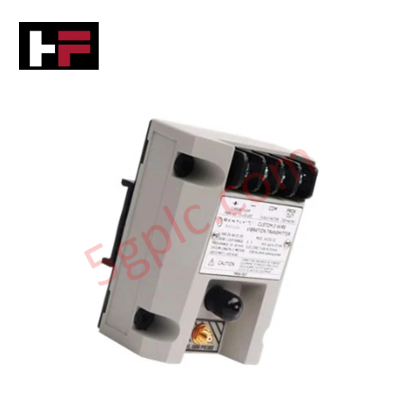
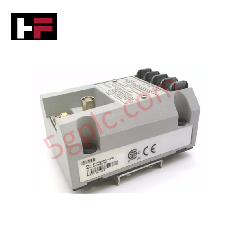
The Bently Nevada 3300/03-02-00, also cataloged as the 3300/03 System Monitor, operates as a dedicated hardware component for system rack power supervision and diagnostic alarm status aggregation within 3300 Series Monitoring System platforms.
Suffix Breakdown & Model Matrix
| Option Field | Code | Configuration Detail |
|---|---|---|
| System Monitor Base | 3300/03 | Core rack system monitor architecture |
| Relay / Feature Option | 02 | Individual relay outputs for OK, Alert, and Danger states |
| Agency Approval Option | 00 | None / Standard uncertified configuration |
Hardware Specifications
| Parameter | Specification |
|---|---|
| Model | 3300/03-02-00 |
| Brand | Bently Nevada |
| Origin | USA |
| Weight | 1.10 kg |
| Dimensions | Standard dual-slot 3300 Series rack module form factor |
| Operating Temp | 0 deg C to +65 deg C (+32 deg F to +149 deg F) |
| Power Consumption | Powered via internal 3300 rack backplane power supply |
| Signal Bandwidth | Direct processing response up to 30 kHz |
| Relay Contacts | Epoxy-sealed Form C relays for systemic rack alarm summary |
| Diagnostics | Continuous backplane bus monitoring, rack power rail supervision, and OK circuit status |
Gap Voltage Validation and Rotor Dynamics Analysis
The 3300/03 System Monitor processes overall rack diagnostics while conditioning dynamic vibration signals routed across the backplane bus. The module continuously verifies DC gap voltage levels from connected proximity probe channels to confirm probe linear center-point biasing near -10 VDC targets. By maintaining rigorous signal path integrity up to 30 kHz output processing frequencies, the unit prevents harmonic signal degradation across high-speed rotor dynamics monitoring loops and enforces effective cross-talk suppression between adjacent monitoring slots.
Frequently Asked Questions
Q: What primary monitoring functions does the 3300/03 System Monitor execute within the rack assembly?
A: The module supervises internal system power rails, coordinates rack-wide Alert and Danger logic summaries, and provides front-panel status indications along with direct dry-contact relay interfaces for plant DCS interlocks.
Q: How does backplane power distribution impact module insertion and removal?
A: Power to the specific rack slot should be disengaged or system power turned off prior to extracting the 3300/03 card to prevent transient voltage spikes across the shared backplane bus.
Field Installation Guidelines
- Disconnect main power to the 3300 rack before sliding the 3300/03 module into its dedicated rack position.
- Align the printed circuit board edges with the top and bottom chassis guide rails inside the enclosure.
- Push the module firmly into the slot until the backplane connectors fully seat into the rear header.
- Tighten the front panel top and bottom retaining screws to establish chassis frame electrical grounding.
- Terminate relay alarm contact outputs using shielded cabling, keeping shield drain wires grounded at a single point to prevent ground loops.
Additional Information
- 100% Genuine Parts: All products are original and authentic, ensuring reliable industrial performance.
- 30-Day Refund Guarantee: Return any in-stock item within 30 days in original, unopened packaging for a full refund (excluding shipping and fees).
- 12-Month Warranty: Covers defects in materials or workmanship; excludes misuse, normal wear, or unauthorized modifications.
- Worldwide Shipping: We ship via USPS, UPS, FedEx, and DHL. Delivery times vary by country and may be subject to customs or import fees.
- Support & Contact: Technical and warranty assistance is available anytime. Contact us here: Contact.
- Purchase Guidance: Check product specifications and compatibility carefully before ordering to ensure proper application.



Tech & Buying Guide

Step-by-Step System Cabinet Health Check Guide for PLC and DCS Infrastructure

Top 5 Operational Advantages of HMIs in Modern Factory Automation
