










Product Details
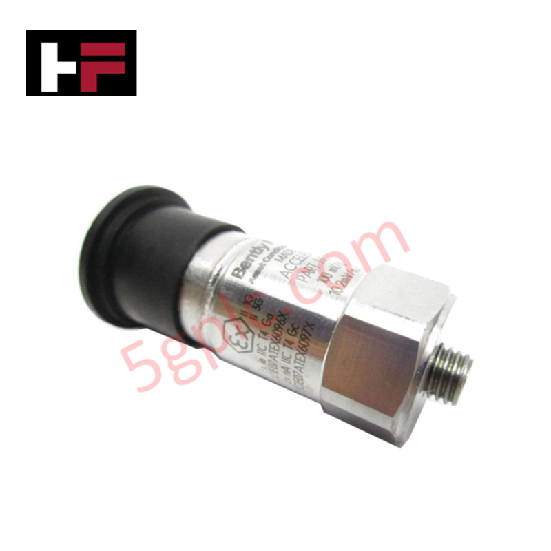
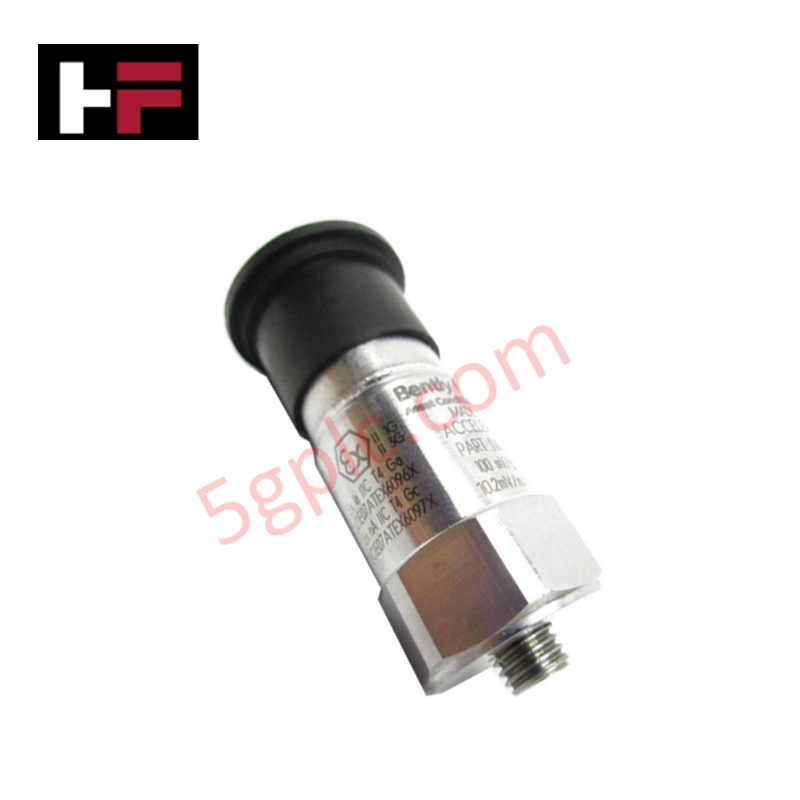
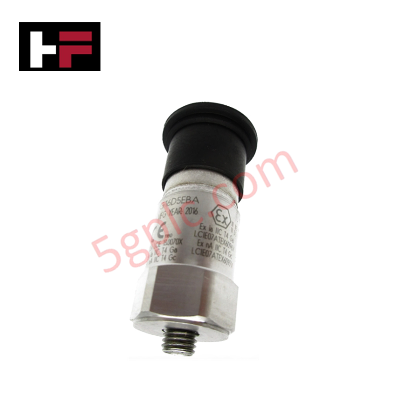
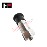
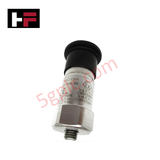
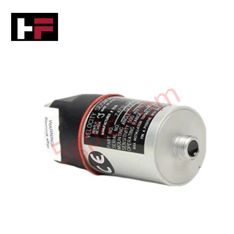
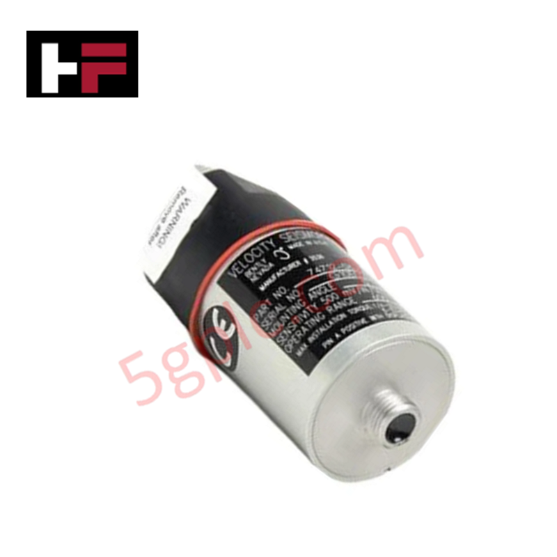
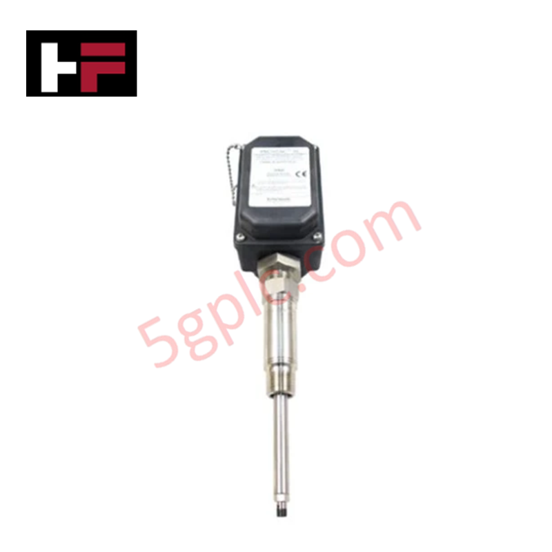
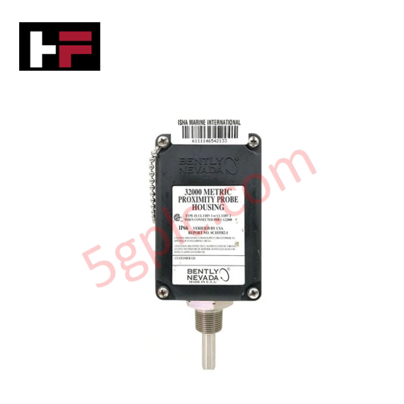
The Bently Nevada 200350-02-00-CN, also cataloged as the 200350 Accelerometer, operates as a dedicated hardware component for piezoelectric seismic vibration detection and dynamic casing acceleration measurement within Bently Nevada Machinery Monitoring Systems.
Suffix Breakdown & Model Matrix
| Option Field | Code | Configuration Detail |
|---|---|---|
| Mounting Stud Option | 02 | 1/4-28 to M8 x 1.25 Beryllium Copper (BeCu) stud |
| Sensitivity Tolerance Option | 00 | 100 mV/g +/- 20% sensitivity tolerance |
| Agency Approval Option | CN | China Hazardous Area Approvals |
Hardware Specifications
| Parameter | Specification |
|---|---|
| Model | 200350-02-00-CN |
| Brand | Bently Nevada |
| Origin | USA |
| Weight | 0.10 kg |
| Dimensions | Standard hex-body piezoelectric accelerometer profile |
| Operating Temp | -54 deg C to +121 deg C |
| Power Consumption | Powered via constant-current loop supply (2 to 10 mA) |
| Nominal Sensitivity | 100 mV/g (10.2 mV/m/s^2) |
| Mounting Stud | 1/4-28 UNF to M8 x 1.25 BeCu |
| Enclosure Sealing | Hermetically sealed stainless steel housing |
Rotor Dynamics and Dynamic Signal Conditioning
The 200350-02-00-CN sensor captures high-frequency casing vibration signals associated with rolling element bearing degradation and gear mesh frequencies. Internal piezoelectric sensing elements generate a charge output proportional to acceleration, which is converted to a low-impedance voltage signal. Proper stud torquing prevents mounting resonance shifts, maintaining frequency response across the rotor dynamics spectrum. Shielded twisted-pair wiring suppresses cross-talk degradation and high-frequency noise interference along field cable paths to the monitoring rack.
Frequently Asked Questions
Q: What mounting stud thread pitch is supplied with the option 02 configuration?
A: Option 02 provides a dual-threaded beryllium copper stud with a 1/4-28 UNF thread on the sensor side and an M8 x 1.25 thread on the machine surface side.
Q: Does the 200350-02-00-CN require an external charge amplifier?
A: No, the sensor contains internal signal conditioning electronics requiring only a standard constant-current power source (2 to 10 mA) over two-wire loop connections.
Field Installation Guidelines
- Prepare the mounting surface by spot-facing a flat, smooth area free of paint, rust, and burrs around the tapped hole.
- Apply a thin layer of silicone grease to the mounting interface to ensure acoustic coupling between the sensor base and machine casing.
- Thread the M8 x 1.25 end of the beryllium copper stud into the machine housing and torque the sensor onto the 1/4-28 stud end according to standard torque limits.
- Route the twisted, shielded two-conductor cable through grounded conduit, avoiding parallel runs next to high-voltage power lines.
- Terminate the cable shield at the monitoring system chassis ground terminal only, leaving the sensor-end shield ungrounded to prevent ground loops.
Additional Information
- 100% Genuine Parts: All products are original and authentic, ensuring reliable industrial performance.
- 30-Day Refund Guarantee: Return any in-stock item within 30 days in original, unopened packaging for a full refund (excluding shipping and fees).
- 12-Month Warranty: Covers defects in materials or workmanship; excludes misuse, normal wear, or unauthorized modifications.
- Worldwide Shipping: We ship via USPS, UPS, FedEx, and DHL. Delivery times vary by country and may be subject to customs or import fees.
- Support & Contact: Technical and warranty assistance is available anytime. Contact us here: Contact.
- Purchase Guidance: Check product specifications and compatibility carefully before ordering to ensure proper application.
Tech & Buying Guide

Essential Motion Control Commands: A Practical Guide for Engineers
Automation engineers often rely on precise position and speed control to drive modern factory machinery. Modern industrial systems, such as Programmable Logic Controllers (PLCs) and Distributed Control Systems (DCS), depend heavily on standardized motion instructions. Mastering these commands ensures operational safety, protects mechanical components, and optimizes cycle times across production lines.
Mastering Modern Industrial Joystick Controls in Heavy Automation
Industrial joysticks play a pivotal role in human-machine interaction across heavy material handling and mobile hydraulics. These tactile controllers translate complex operator movements into precise electrical signals for PLCs, motion controllers, and DCS networks. Consequently, selecting and installing the right joystick architecture ensures operator safety, reduces fatigue, and optimizes equipment performance.

Navigating Industrial Automation Failures: Types, Causes, and Mitigation Strategies
Modern manufacturing relies heavily on automated control systems to maximize throughput and maintain product quality. However, unplanned downtime in industrial automation can cost facility operators thousands of dollars per hour. Understanding how programmable logic controllers (PLCs), distributed control systems (DCS), and field instrumentation fail empowers engineering teams to implement robust preventive maintenance strategies.