


Product Details
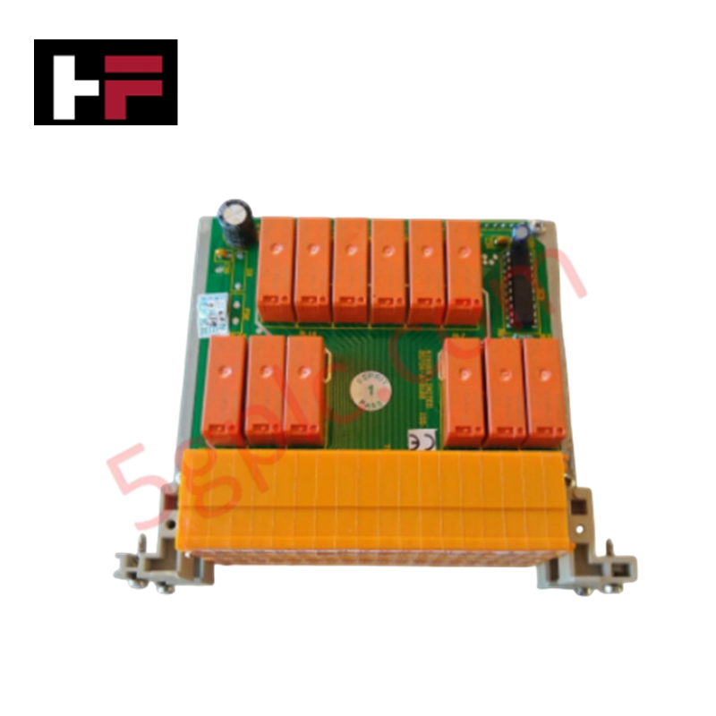
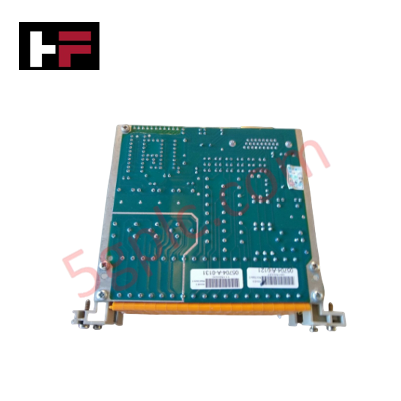
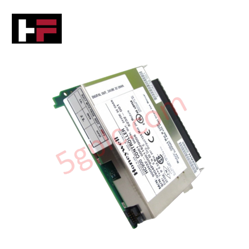
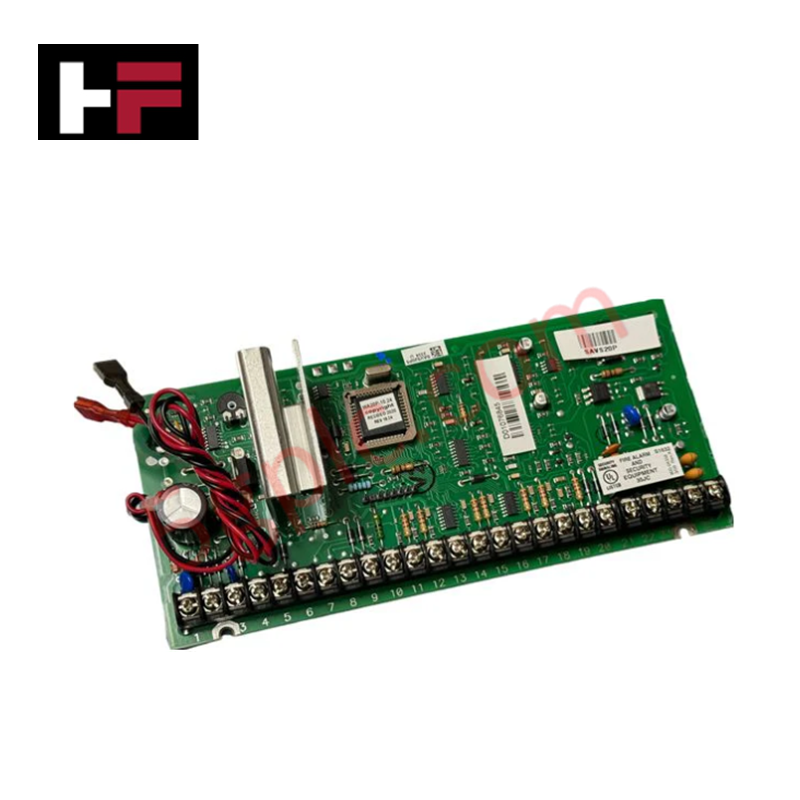
Configured for high-density discrete output management in System 57 architectures, the Honeywell 05704-A-0131 (05704-A-0131 Relay Interface Assembly) provides direct physical execution of sensor-to-logic switching. The module serves as a primary relay interface utilized to execute alarm routing and auxiliary control switching across System 57 platforms.
Hardware Specifications
| Parameter | Specification |
|---|---|
| Model | 05704-A-0131 |
| Brand | Honeywell |
| Origin | United States |
| Weight | 0.28 kg |
| Dimensions | 8.8 x 22.7 x 17.5 cm |
| Relay Configuration | 12 SPCO, 4 SPST (16 total) |
DCS Process Control and Connectivity
The 05704-A-0131 provides a high-density switching solution, incorporating 16 independent relays to facilitate signal isolation between system controllers and external field devices. The assembly supports channel-to-channel isolation on the relay output side, which prevents cross-channel electromagnetic interference (EMI) and electrical noise propagation. To maintain signal precision, the module architecture ensures that the relay drive circuitry operates independently of the primary process control loop, mitigating the risk of induced ground loops. Integrated design features support 4-20 mA HART loop protocol environments by ensuring that the relay interface maintains signal loop continuity and noise floor stability during high-speed switching events.
Frequently Asked Questions
Q: Is this module capable of hot-swapping during active system operation?
A: No. The 05704-A-0131 is not designed for hot-swapping. Removal or installation while the system is energized can result in backplane transient spikes, potential damage to the relay control logic, and unintended activation of the connected field outputs.
Q: Can the SPCO and SPST relays be configured for independent trigger logic?
A: Relay trigger logic is determined by the central controller configuration. Ensure that the controller output map is correctly mapped to the specific contact type (SPCO vs SPST) for each relay position to ensure correct field device actuation.
Field Installation Guidelines
- Verify the system is de-energized and confirm isolation from all power sources before proceeding with installation.
- Align the relay interface assembly with the system chassis guides and seat the backplane connector firmly to ensure low-resistance connectivity.
- Secure the module mounting fasteners to the rack frame to provide a solid chassis ground, which is required for effective EMI mitigation and shielding.
- Verify that field wiring cross-section complies with terminal block specifications for the specific System 57 rack type.
- Perform a functional output test using the system diagnostic interface to confirm that each relay responds correctly to programmed logic commands before placing the loop into service.
Additional Information
- 100% Genuine Parts: All products are original and authentic, ensuring reliable industrial performance.
- 30-Day Refund Guarantee: Return any in-stock item within 30 days in original, unopened packaging for a full refund (excluding shipping and fees).
- 12-Month Warranty: Covers defects in materials or workmanship; excludes misuse, normal wear, or unauthorized modifications.
- Worldwide Shipping: We ship via USPS, UPS, FedEx, and DHL. Delivery times vary by country and may be subject to customs or import fees.
- Support & Contact: Technical and warranty assistance is available anytime. Contact us here: Contact.
- Purchase Guidance: Check product specifications and compatibility carefully before ordering to ensure proper application.


Tech & Buying Guide

Why 24V DC Power Supplies Standardize Modern Industrial Automation
Industrial control cabinets worldwide rely on 24V DC as the universal power standard for field instrumentation, sensors, and controllers. Walk into any manufacturing plant, and you will find PLCs, human-machine interfaces (HMIs), and smart actuators running on extra-low voltage DC. Standardizing on 24V DC enhances operational safety, lowers cabinet footprint, and maintains steady control performance across factory networks.

Essential Motion Control Commands: A Practical Guide for Engineers
Automation engineers often rely on precise position and speed control to drive modern factory machinery. Modern industrial systems, such as Programmable Logic Controllers (PLCs) and Distributed Control Systems (DCS), depend heavily on standardized motion instructions. Mastering these commands ensures operational safety, protects mechanical components, and optimizes cycle times across production lines.

Mastering Modern Industrial Joystick Controls in Heavy Automation
Industrial joysticks play a pivotal role in human-machine interaction across heavy material handling and mobile hydraulics. These tactile controllers translate complex operator movements into precise electrical signals for PLCs, motion controllers, and DCS networks. Consequently, selecting and installing the right joystick architecture ensures operator safety, reduces fatigue, and optimizes equipment performance.