










Product Details
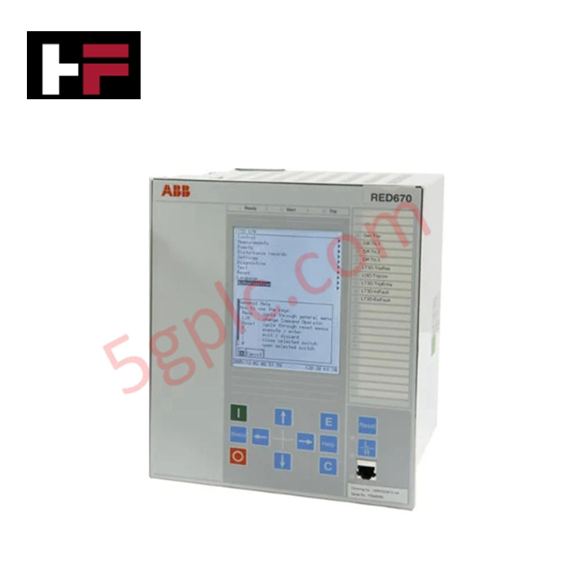
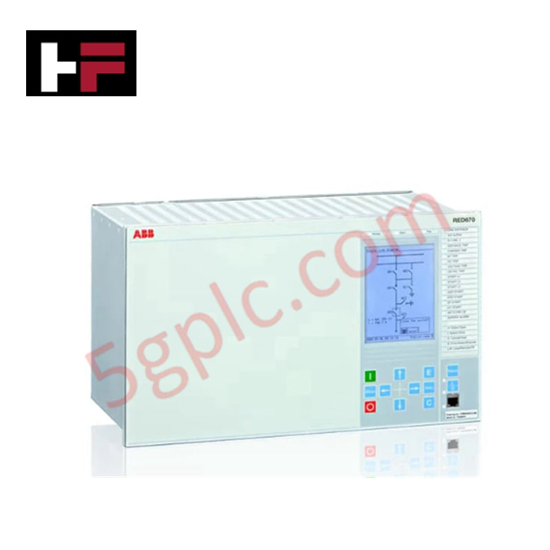
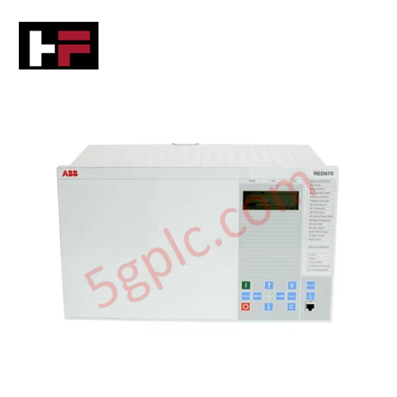
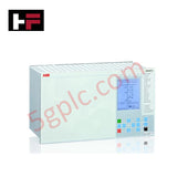
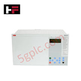
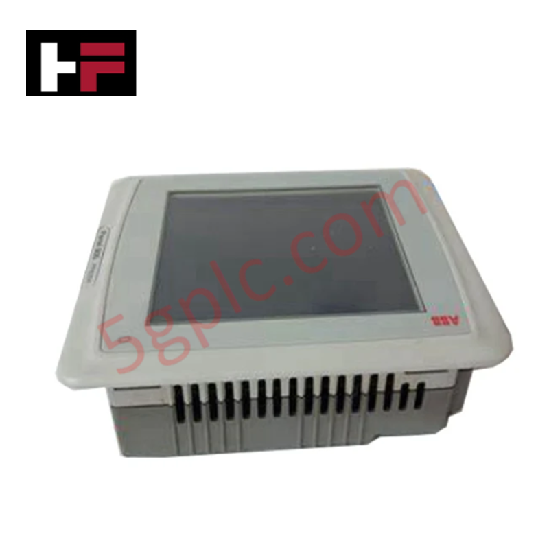
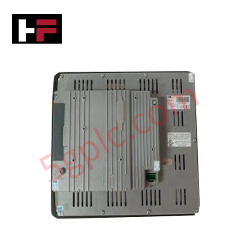
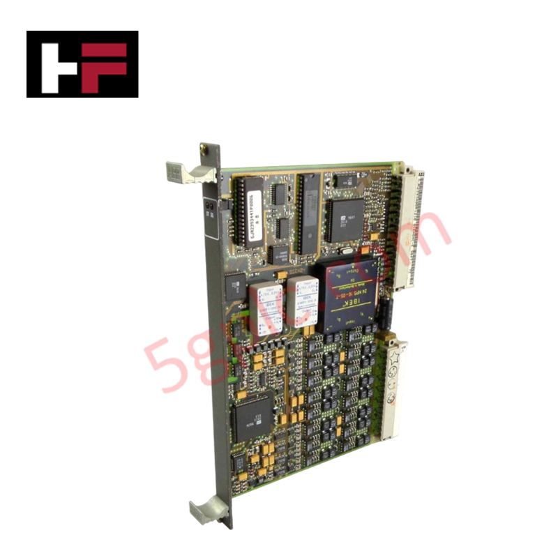
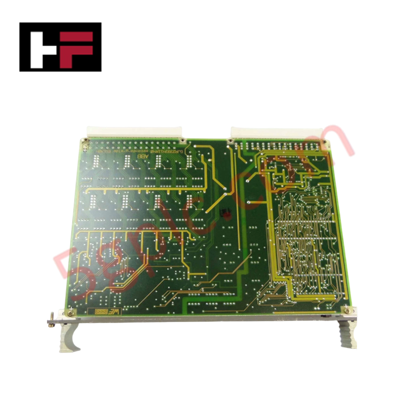
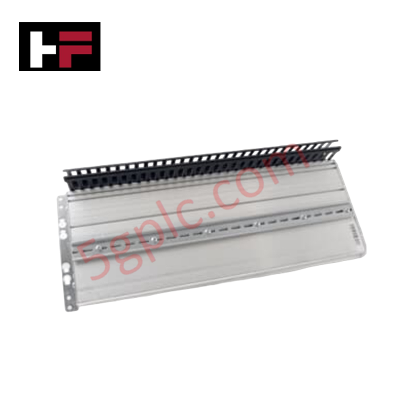
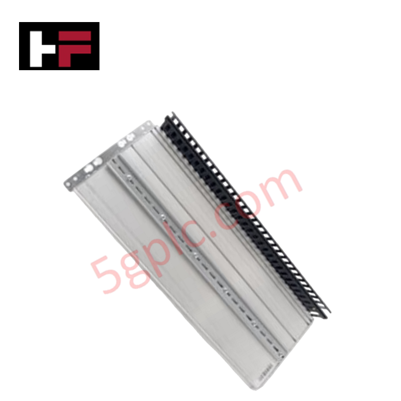
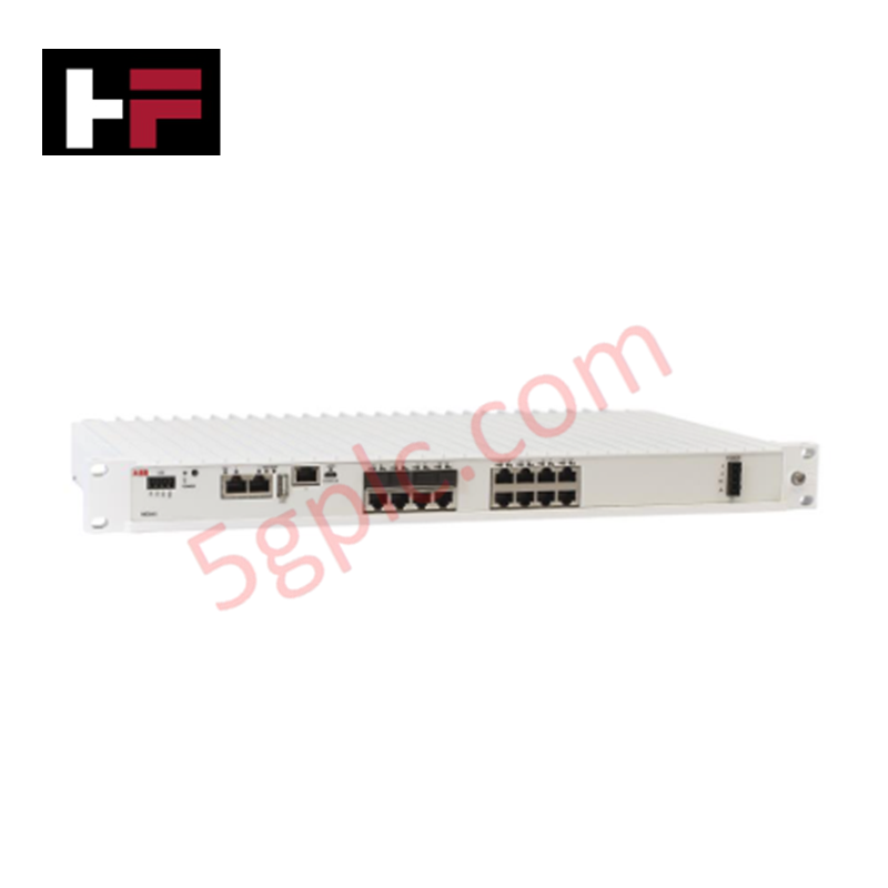
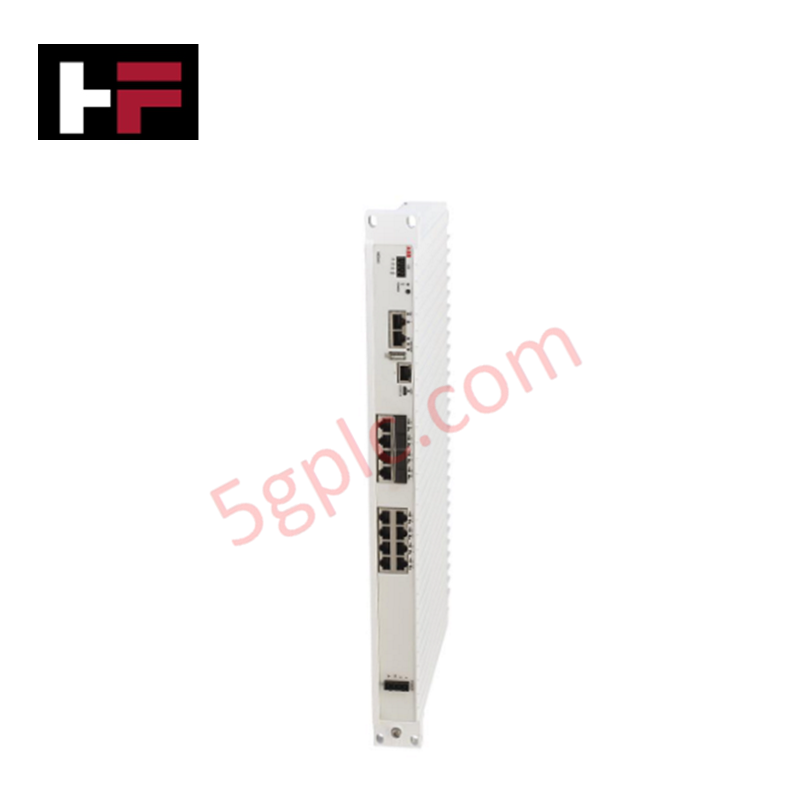
Configured for high-speed differential phase calculation and line fault isolation in high-voltage switchgear networks, the ABB 1MRK002810-XE (RED670 Line Differential Protection Relay) provides direct physical/electrical execution. The hardware subsystem digitizes multi-phase current vectors, evaluates longitudinal current differentials across local and remote terminals via optical links, updates IEC 61850 GOOSE data structures, and drives high-speed trip relays to isolate fault zones.
Hardware Specifications
| Parameter | Specification |
|---|---|
| Model | RED670 1MRK002810-XE |
| Brand | ABB |
| Origin | Sweden |
| Weight | 3.5 kg |
| Dimensions | 230 mm x 160 mm x 100 mm |
| Rated Voltage | Up to 765 kV |
| Rated Current | Up to 5 000 A |
| Protection Accuracy | 0.2% |
| Operating Temp | -40 to +70 deg C |
| Operating Humidity | 5% to 95% RH (Non-condensing) |
| Communication Protocols | IEC 61850-8-1 (GOOSE, Client-Server MMS) |
| Product Type | Protection Relays |
Profinet / EtherNet/IP Deterministic Networks and Firmware Flash Compatibility
The processing intervals of the execution pipeline inside the ABB RED670 1MRK002810-XE interface natively with highly deterministic backplane bus communication velocity metrics. When station-level integration routes raw metrics or protection parameters over upper-level industrial ethernet topologies, such as Profinet or EtherNet/IP deterministic networks, the module handles multi-channel register maps without adding propagation delay. The modular architecture prevents cycle timing degradation during expansion phases that require intensive I/O density scaling, maintaining synchronous communication across all sub-rack components provided that field upgrades strictly verify master firmware flash compatibility profiles.
Frequently Asked Questions
Q: Can the communication interface modules or analog input blocks of the RED670 be hot-swapped under live operational conditions?
A: No. The terminal does not support hot-swap operations while energized. Isolating any sub-assembly or removing connections while the auxiliary power line or secondary current transformer (CT) links are live risks inductive voltage transients, breakdown of current terminal paths, and immediate controller error states.
Q: How is a network or protocol connection loss managed when utilizing IEC 61850 GOOSE communication?
A: Communication status is monitored via continuous heartbeat polling. If a communication network dropout is flagged on the deterministic network layer, the hardware switches to local fallback protection modes and registers a diagnostic event log within the host system register maps.
Field Installation Guidelines
- ESD Compliance Methods: Plant technicians must wear a fully checked, grounded electrostatic discharge (ESD) wrist strap prior to handling internal module sub-cards or configuration jumpers to avoid micro-circuit breakdown.
- Current Transformer Wiring Configuration: Ensure all secondary current transformer circuits are physically shorted via dedicated shorting blocks prior to terminating lines into the relay current input pins to eliminate hazardous open-loop high voltage risks.
- Control Cable Isolation Protocol: Route all optical fiber lines, station bus ethernet cables, and low-voltage binary signaling wires through separate shielded wireways. Maintain a physical clearance of at least 100 mm from primary high-voltage AC conductors to block inductive noise re-coupling.
- Housing Bolt Torque Verification: Mount the 3.5 kg enclosure onto the designated rack panel cutout. Torque all faceplate retention studs evenly to ensure structural ground connection continuity and maintain the specified IP protective boundaries against dust and moisture ingress.
Additional Information
- 100% Genuine Parts: All products are original and authentic, ensuring reliable industrial performance.
- 30-Day Refund Guarantee: Return any in-stock item within 30 days in original, unopened packaging for a full refund (excluding shipping and fees).
- 12-Month Warranty: Covers defects in materials or workmanship; excludes misuse, normal wear, or unauthorized modifications.
- Worldwide Shipping: We ship via USPS, UPS, FedEx, and DHL. Delivery times vary by country and may be subject to customs or import fees.
- Support & Contact: Technical and warranty assistance is available anytime. Contact us here: Contact.
- Purchase Guidance: Check product specifications and compatibility carefully before ordering to ensure proper application.
Tech & Buying Guide

Executing a PLC System Site Acceptance Test (SAT): The Definitive Engineering Guide
The transition of a Programmable Logic Controller (PLC) cabinet from a controlled factory floor to a volatile plant environment represents a critical milestone in factory automation. While a Factory Acceptance Test (FAT) validates standalone hardware compliance under ideal conditions, it cannot replicate real-world process dynamics. Therefore, deploying an industrial automation system requires a rigorous Site Acceptance Test (SAT) to verify total loop integrity, field wiring wiring metrics, and process control parameters before final customer handover.

Advanced Integration: Master Protocol for VFD Commissioning and Testing
Deploying variable frequency drives (VFDs) requires precise execution during the initial commissioning phase. Junior automation engineers often find the first power-up sequence intimidating. However, following a rigorous engineering framework ensures equipment safety and system reliability. Proper startup procedures protect both the drive electronics and the connected motor.

Optimizing Factory Automation: The Definitive Guide to VFD Preventive Maintenance
Variable Frequency Drives (VFDs) serve as critical assets in modern industrial automation. These power electronic devices regulate electric motors by adjusting the supplied frequency and voltage. Consequently, industries utilize VFDs to reduce energy consumption and optimize process control. Major manufacturers like Siemens, ABB, and Yaskawa design highly efficient drives. However, sustained efficiency requires a rigorous preventive maintenance program.