










Product Details
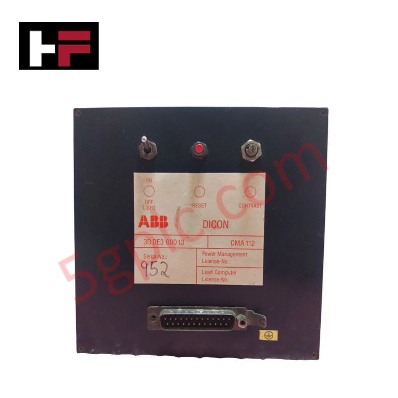
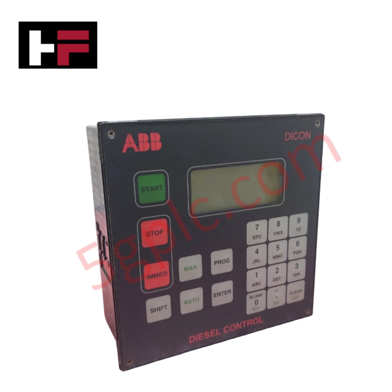
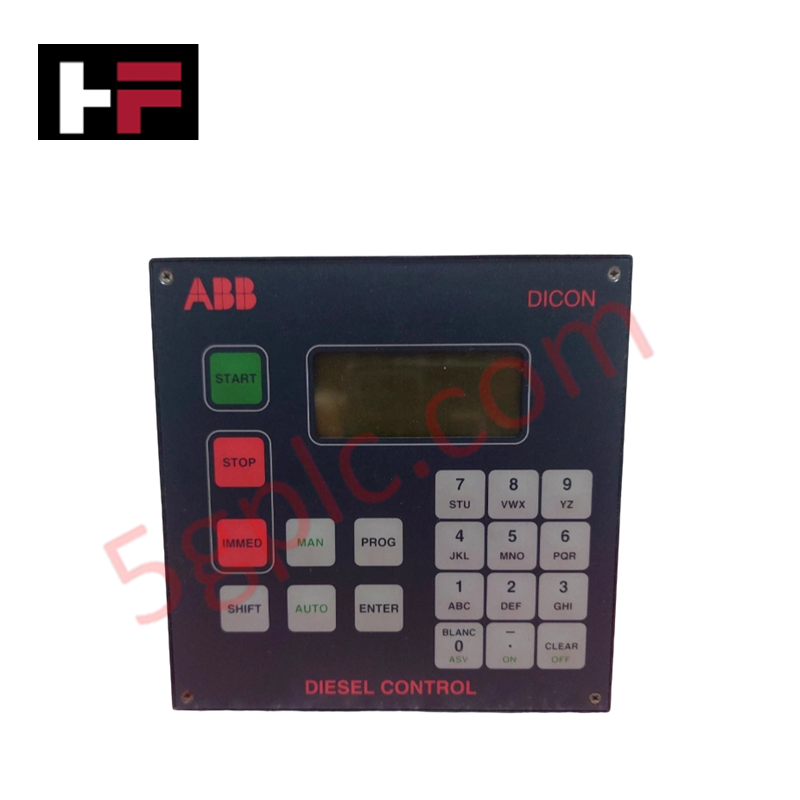
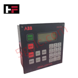
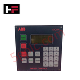
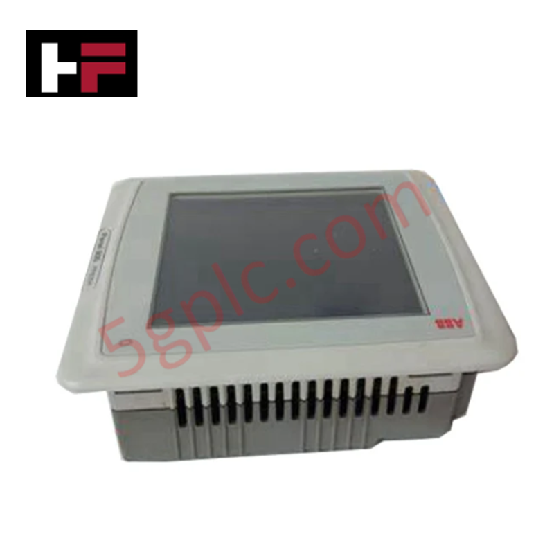
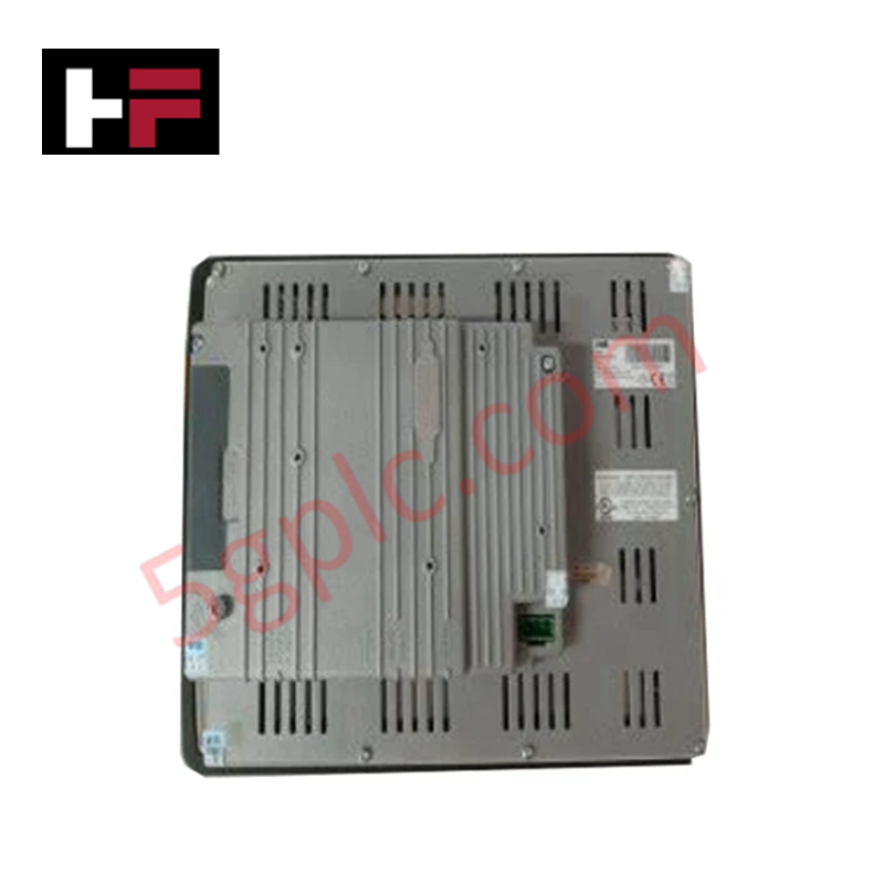
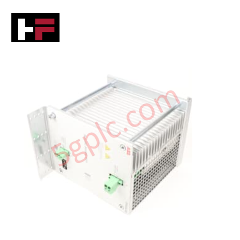
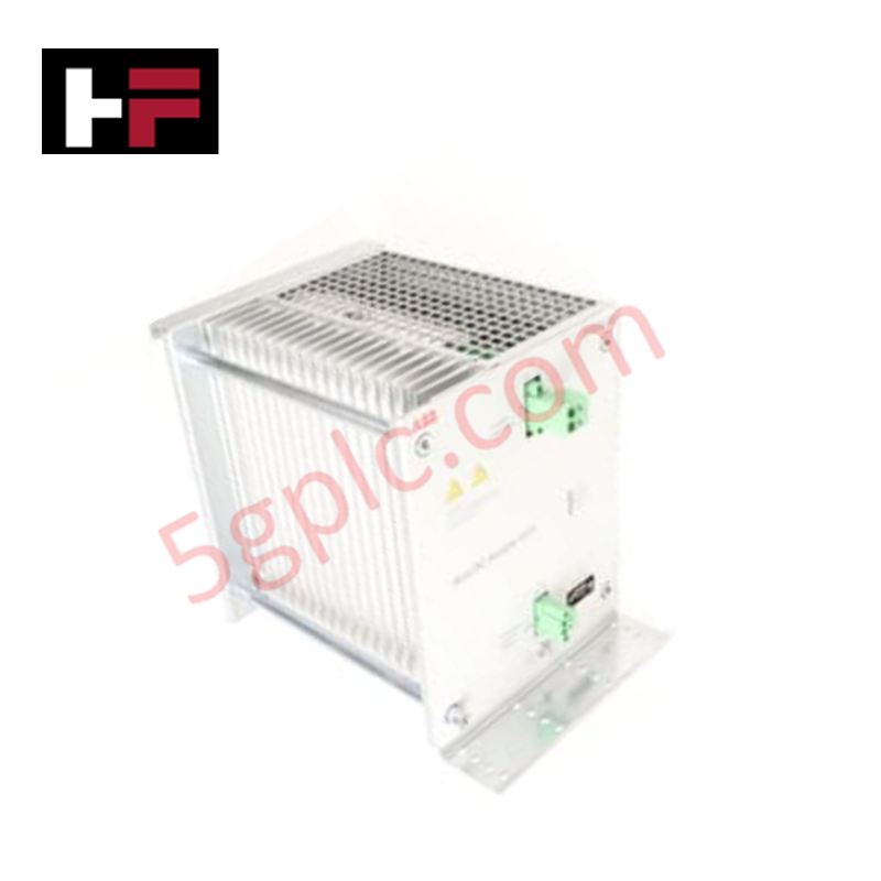
The ABB CMA 112 3D DE3 000 13 serves as the primary CMA 112 Diesel Engine Control Display Panel utilized to execute real-time monitoring and precision control of diesel generator sets across industrial engine platforms. The assembly interfaces directly with discrete and serial engine instrumentation channels, processes multi-protocol fuel state and speed vectors, and outputs algorithmic actuation signals via integrated communication interfaces to regulate physical prime mover sub-elements under changing load balances.
Hardware Specifications
| Parameter | Specification |
|---|---|
| Model | CMA 112 3D DE3 000 13 (CMA112) |
| Brand | ABB |
| Origin | Sweden / Germany (Standard production matrix baseline) |
| Weight | 0.7 kg |
| Dimensions | 152 mm x 152 mm x 76 mm |
| Display Size | 12-inch LCD touchscreen |
| Resolution | 1280 x 800 pixels |
| Memory | 256 MB RAM, 512 MB Flash |
| Communication Interfaces | RS-485, CANopen, Ethernet |
| Power Supply | 12 VDC / 24 VDC options |
| Operating Temp | -20 to +50 deg C |
| Product Type | Diesel Engine Control Display Panels |
Profinet / EtherNet/IP Deterministic Networks and I/O Density Scaling
The internal runtime environment of the ABB CMA 112 3D DE3 000 13 bridges localized machine-level protocols directly into higher-tier system architectures. When engine parameters are aggregated from the CANopen interface and broadcasted over Profinet or EtherNet/IP deterministic networks via the onboard Ethernet adapter, the data packet scheduling mechanisms prevent frame latency spikes. The display and memory architecture handle sudden structural data point updates smoothly during periods of rapid system growth or broad I/O density scaling, provided all sub-node telemetry modifications maintain matching host controller firmware flash compatibility parameters.
Frequently Asked Questions
Q: Can the power terminals or communication interface cables of the CMA 112 panel be hot-swapped while the diesel generator is actively running?
A: No. The unit must not be disconnected while auxiliary power or live bus communication is active. Removing serial or power contacts under active engine operation risks high-voltage inductive arcing, causing total data packet dropouts, sudden engine shutdown interlocks, or physical breakdown of the internal transceivers.
Q: How is a memory synchronization failure or firmware flash compatibility conflict indicated?
A: System hardware conflicts are registered via automated boot diagnostics on the 12-inch LCD interface. If a flash validation error occurs, hardware parameter blocks must be verified against the core engine controller profile to match required runtime communication constraints.
Field Installation Guidelines
- ESD Handling Measures: Technical field operators must wear a properly connected and grounded electrostatic discharge (ESD) wrist strap prior to interfacing with unshielded backplane connections or wiring blocks to block latent tracking breakdown.
- Panel Cutout Optimization: Mount the 0.7 kg enclosure flush within a prepared, low-vibration metal cutout. Secure all integrated edge clamps evenly to achieve complete gasket seal seating, mitigating moisture ingress and panel warping.
- Control Conduit and Routing Rules: Group and route the RS-485, CANopen, and Ethernet cables inside separate low-voltage wireways. Maintain a physical distance of at least 100 mm from three-phase AC generator outputs or high-current motor starter links to prevent inductive noise injection.
- Power Supply Conditioning: Verify that external 12 VDC or 24 VDC auxiliary power sources sit within design-specified noise tolerances. Use short, dedicated ground straps to connect the housing ground terminal directly to the machine chassis ground point.
Additional Information
- 100% Genuine Parts: All products are original and authentic, ensuring reliable industrial performance.
- 30-Day Refund Guarantee: Return any in-stock item within 30 days in original, unopened packaging for a full refund (excluding shipping and fees).
- 12-Month Warranty: Covers defects in materials or workmanship; excludes misuse, normal wear, or unauthorized modifications.
- Worldwide Shipping: We ship via USPS, UPS, FedEx, and DHL. Delivery times vary by country and may be subject to customs or import fees.
- Support & Contact: Technical and warranty assistance is available anytime. Contact us here: Contact.
- Purchase Guidance: Check product specifications and compatibility carefully before ordering to ensure proper application.
Tech & Buying Guide

Executing a PLC System Site Acceptance Test (SAT): The Definitive Engineering Guide
The transition of a Programmable Logic Controller (PLC) cabinet from a controlled factory floor to a volatile plant environment represents a critical milestone in factory automation. While a Factory Acceptance Test (FAT) validates standalone hardware compliance under ideal conditions, it cannot replicate real-world process dynamics. Therefore, deploying an industrial automation system requires a rigorous Site Acceptance Test (SAT) to verify total loop integrity, field wiring wiring metrics, and process control parameters before final customer handover.

Advanced Integration: Master Protocol for VFD Commissioning and Testing
Deploying variable frequency drives (VFDs) requires precise execution during the initial commissioning phase. Junior automation engineers often find the first power-up sequence intimidating. However, following a rigorous engineering framework ensures equipment safety and system reliability. Proper startup procedures protect both the drive electronics and the connected motor.

Optimizing Factory Automation: The Definitive Guide to VFD Preventive Maintenance
Variable Frequency Drives (VFDs) serve as critical assets in modern industrial automation. These power electronic devices regulate electric motors by adjusting the supplied frequency and voltage. Consequently, industries utilize VFDs to reduce energy consumption and optimize process control. Major manufacturers like Siemens, ABB, and Yaskawa design highly efficient drives. However, sustained efficiency requires a rigorous preventive maintenance program.