










Product Details
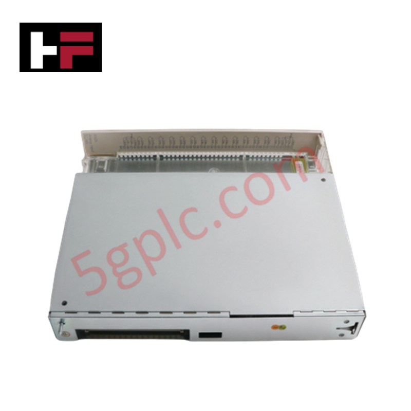
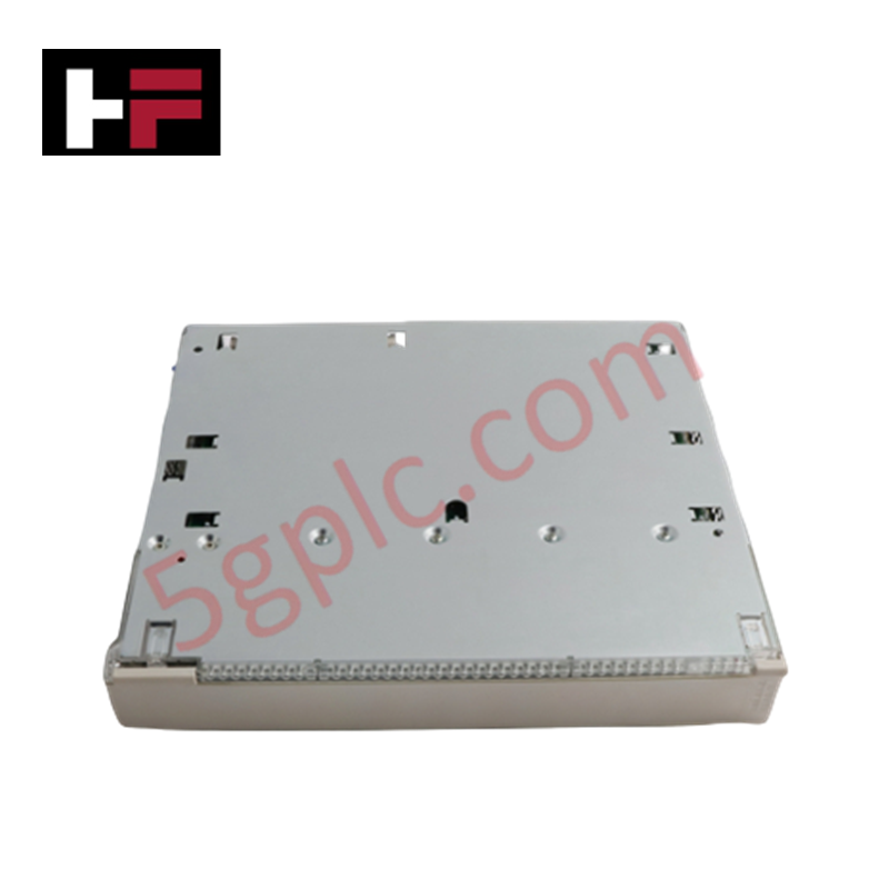
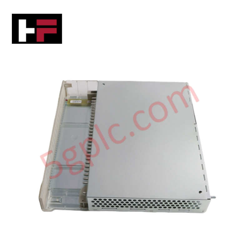
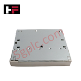
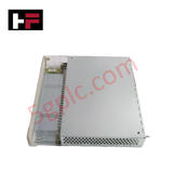
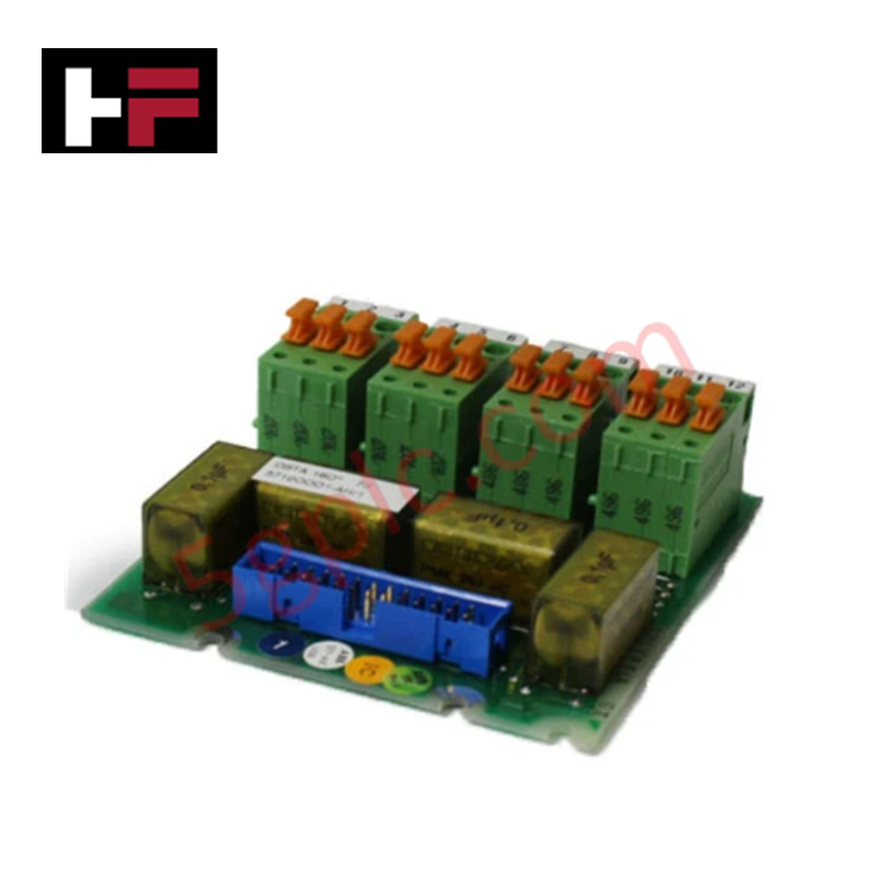
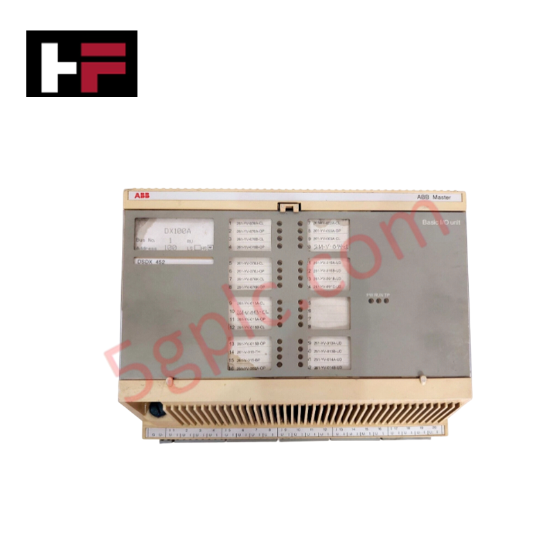
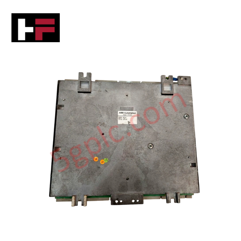
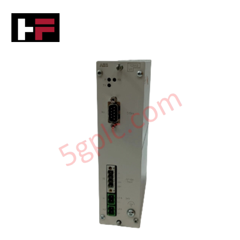
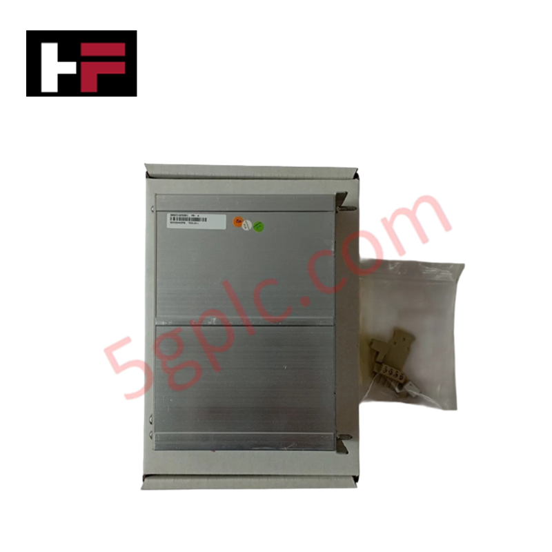
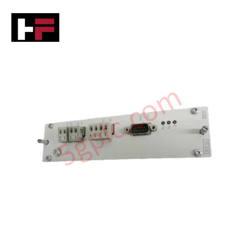
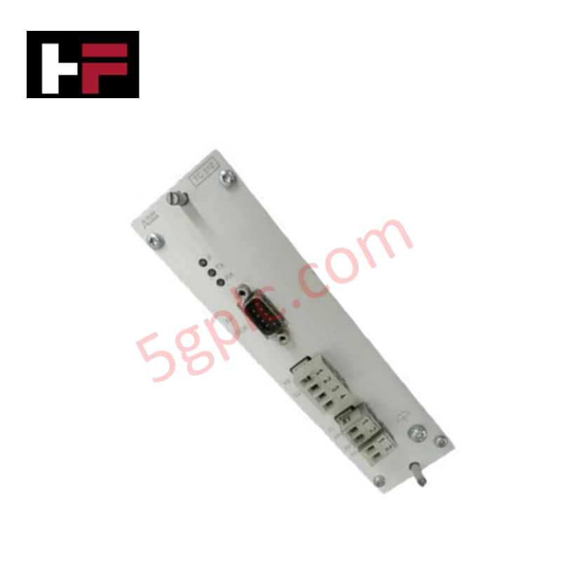
Configured for multi-channel analog signal acquisition in ABB Advant controller environments, the ABB AI620 3BHT300005R1 (AI620 Analog Input Module) provides direct physical/electrical execution across high-density sensor loops.
Hardware Specifications
| Parameter | Specification |
|---|---|
| Model | AI620 (3BHT300005R1) |
| Brand | ABB |
| Origin | Sweden |
| Weight | 1.28 kg |
| Dimensions | 40 mm x 252 mm x 273 mm |
| Operating Temp | 0 to 55 deg C |
| Power Consumption | Power supplied via system backplane bus |
| Input Resolution | 12 bit |
| Number of Channels | 16 channels (32 channel physical connection configuration) |
| Channel Type | Analog Input (AI) |
| WEEE Category | 5. Small Equipment (No External Dimension More Than 50 cm) |
Backplane Bus Communication Velocity and Firmware Flash Compatibility
The AI620 analog input module processes multi-channel analog signals without degrading backplane bus communication velocity across the host controller rack. Integrated analog-to-digital converters execute continuous signal conditioning with 12 bit resolution while maintaining high-speed bus arbitration. Standardized firmware flash compatibility across parent Advant controller subracks ensures deterministic scan cycles, accurate error logging, and balanced I/O density scaling during parallel loop updates.
Frequently Asked Questions
Q: What resolution does the internal analog-to-digital converter execute on the AI620 module?
A: The AI620 uses a 12 bit resolution ADC circuit for analog input signal digitizing.
Q: How is primary operating power supplied to the AI620 module logic?
A: Power is drawn directly through the backplane motherboard connector when seated in the rack chassis.
Q: What precautions are necessary regarding signal cable shield termination?
A: Shielded twisted-pair field cables must be connected to designated ground buses at the termination unit to suppress common-mode electromagnetic interference.
Field Installation Guidelines
- Isolate power feeds to the subrack before inserting or withdrawing the AI620 module.
- Verify that the backplane connector pins are clean and free from mechanical obstruction.
- Align the module card edges with the chassis guide slots and slide the board inward until the rear connector seats into the backplane.
- Tighten the module front panel thumbscrews to secure mechanical attachment and ensure functional grounding continuity.
- Connect field sensor wiring via approved terminal blocks, ensuring signal polarity and shield grounding adhere to system wiring diagrams.
Additional Information
- 100% Genuine Parts: All products are original and authentic, ensuring reliable industrial performance.
- 30-Day Refund Guarantee: Return any in-stock item within 30 days in original, unopened packaging for a full refund (excluding shipping and fees).
- 12-Month Warranty: Covers defects in materials or workmanship; excludes misuse, normal wear, or unauthorized modifications.
- Worldwide Shipping: We ship via USPS, UPS, FedEx, and DHL. Delivery times vary by country and may be subject to customs or import fees.
- Support & Contact: Technical and warranty assistance is available anytime. Contact us here: Contact.
- Purchase Guidance: Check product specifications and compatibility carefully before ordering to ensure proper application.
Tech & Buying Guide

Understanding VFD Mechanical Brake Logic and Control in Industrial Automation
Variable Frequency Drives (VFDs) play a crucial role in modern industrial automation by controlling motor speed, torque, and acceleration. However, high-inertia loads and vertical lifting systems require precise mechanical braking logic to ensure operational safety and prevent equipment damage.

Why Programmable Logic Controllers Drop into Stop Mode: An Expert Analysis
Industrial automation systems rely heavily on Programmable Logic Controllers (PLCs) to maintain uninterrupted production. When a PLC unexpectedly shifts from Run to Stop mode, whole manufacturing lines stall.
As control systems evolve across modern factory automation, understanding the root causes of these interruptions helps engineers minimize costly downtime. This technical guide breaks down why PLCs trip into Stop mode and provides practical strategies to mitigate system faults.

Understanding Root Causes of Unplanned PLC Stop Mode in Industrial Automation
Modern Programmable Logic Controllers manage execution through distinct operational states: Run, Stop, Start-Up, and Hold. During power-up, a controller initializes memory registers within Stop mode before briefly transitioning to Start-Up mode. During this phase, internal self-diagnostics evaluate system integrity across hardware and user programs. If the controller detects no critical faults, it enters Run mode to execute the control program continuously. However, any severe system anomaly forces the CPU back into Stop mode immediately to prevent erratic machine behavior across the plant floor.