


Product Details
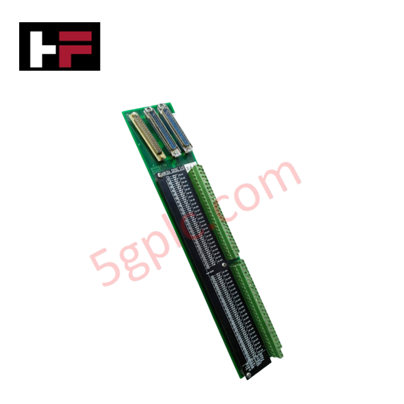
Configured for discrete and analog signal interface in MicroNet control platforms, the Woodward 5501-367 (5501-367 Simplex LV Discrete FTM) provides direct physical/electrical execution of signal conditioning for monitoring and control circuits.
Hardware Specifications
| Parameter | Specification |
|---|---|
| Model | 5501-367 |
| Brand | Woodward |
| Origin | USA |
| Weight | 9.11 lbs |
| Dimensions | 8.75 x 14.625 x 5.375 inches |
| Operating Temp | 55 deg C |
| Power Consumption | 14 W |
| Input Voltage Rating | 18-32 VDC (27.4 A max) |
| Output Voltage Rating | 24 VDC, 16 A |
| Signal to Actuator | 0-200 mA |
| Network Isolation | 1000 Vrms (0-60 Hz) |
Harmonic Distortion Suppression
The 5501-367 module incorporates specialized signal conditioning to maintain loop integrity when driving inductive loads such as solenoids and relays. The architecture utilizes filtering stages to achieve harmonic distortion suppression, ensuring that switching noise generated by the output channels does not propagate into the sensitive control logic. Furthermore, the 1000 Vrms network isolation barrier protects the internal processor bus from transient spikes originating on the field-side wiring, facilitating a stable actuator loop feedback response. This isolation is critical for maintaining signal fidelity across the four input channels, which support a mix of switch contact, 4-20 mA current loop, and voltage-level signals.
Frequently Asked Questions
Q: Are the four output channels independently capable of driving high-current loads?
A: Yes, each of the four output channels can source up to 2 A at 24 VDC. When operating multiple channels simultaneously, ensure the total load does not exceed the aggregate power supply capacity to prevent thermal degradation.
Q: Is the FTM compatible with hot-swapping procedures?
A: The module is not designed for hot-swapping while the control system is powered. All power must be isolated from the 18-32 VDC input terminals before removal or insertion to prevent arcing and damage to the backplane communication contacts.
Field Installation Guidelines
- Mounting: Install the FTM in a clean, ventilated enclosure. The 8.75 x 14.625 x 5.375 inch footprint requires adequate clearance for cable management and heat dissipation at the rated 55 deg C operating temperature.
- Wiring: Separate low-voltage signal wiring (4-20 mA) from high-current output lines (24 VDC, 2 A) to mitigate crosstalk. Use shielded cables for all input channels and terminate shields at the designated chassis grounding point.
- Power Connection: Verify the 18-32 VDC supply polarity before landing wires on the power input terminals. The use of an external overcurrent protection device sized for the 27.4 A maximum input rating is required.
- Validation: During commissioning, verify that the input channels are correctly scaled for the specific sensor type (voltage vs. current). Test each output channel individually to confirm correct actuation of field devices before enabling the automated control sequence.
Additional Information
- 100% Genuine Parts: All products are original and authentic, ensuring reliable industrial performance.
- 30-Day Refund Guarantee: Return any in-stock item within 30 days in original, unopened packaging for a full refund (excluding shipping and fees).
- 12-Month Warranty: Covers defects in materials or workmanship; excludes misuse, normal wear, or unauthorized modifications.
- Worldwide Shipping: We ship via USPS, UPS, FedEx, and DHL. Delivery times vary by country and may be subject to customs or import fees.
- Support & Contact: Technical and warranty assistance is available anytime. Contact us here: Contact.
- Purchase Guidance: Check product specifications and compatibility carefully before ordering to ensure proper application.


Tech & Buying Guide

Understanding Dry Contacts in PLC Wiring: An Industrial Automation Guide
Mastering contact switching principles is essential for reliable control panels. Field devices and PLCs interface through dry or wet contacts. This technical guide examines the mechanics of dry contacts, explores their wiring architectures, and evaluates their key advantages in industrial automation.

Ultimate Commissioning Checklist for Industrial Automation Systems: An Engineering Guide
Commissioning is the most decisive phase of an industrial automation project, transforming control hardware and software into an operational facility. Thorough testing prevents costly startup delays and builds customer confidence. This guide covers essential checklists, electrical standards, and best practices.

Redundant Automation Systems: Core Architecture, Business Value, and Technical Advantages
Unplanned downtime poses a major financial threat to process manufacturing. To prevent costly interruptions, engineers deploy redundant PLC and DCS architectures that ensure continuous operation when hardware fails. This technical guide explores redundancy principles, critical system nodes, and real-world scenarios.