


Product Details
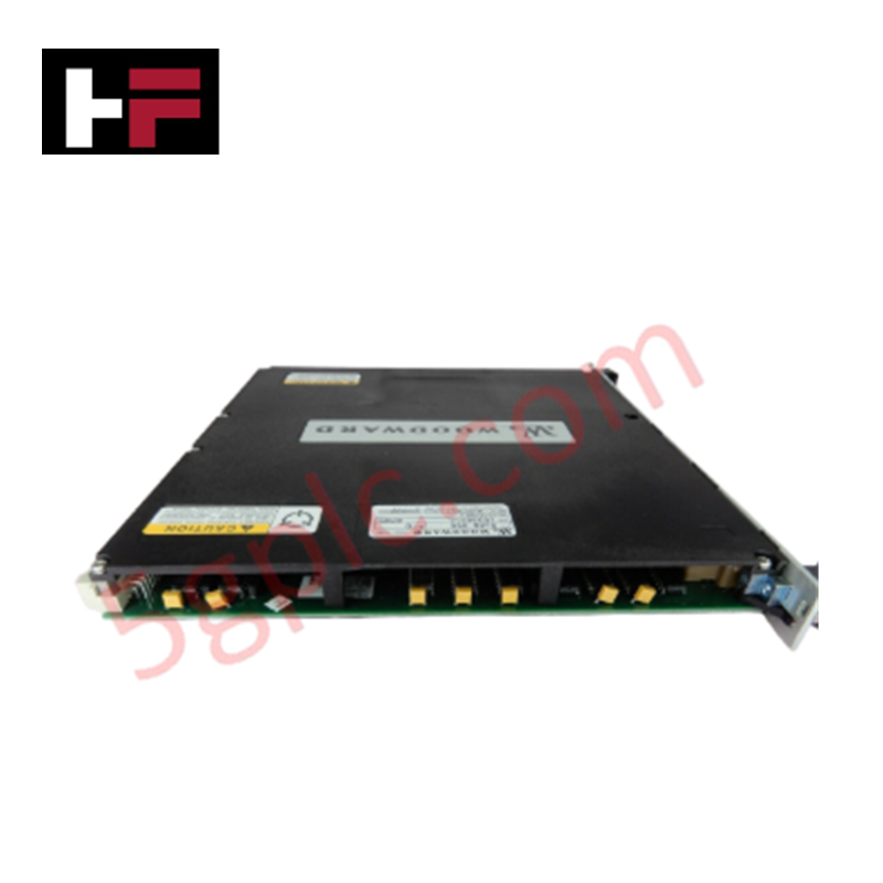
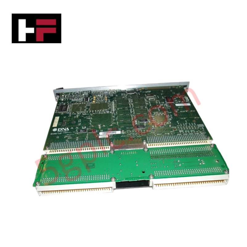
The Woodward 5466-411, also cataloged as the 5466-411 Micronet Ethernet Module, operates as a dedicated hardware component for deterministic network communication and data exchange within MicroNet Digital Control Series platforms.
Hardware Specifications
| Parameter | Specification |
|---|---|
| Model | 5466-411 |
| Brand | Woodward |
| Origin | USA |
| Weight | Not specified |
| Dimensions | 9.50 x 10.50 x 1.00 inches |
| Operating Temp | -40 to 85 deg F |
| Power Consumption | Not specified |
| Input Voltage | 110 VAC / 125 VDC (80-150 V range) |
| Output Voltage Rating | 24 VDC, 16 A |
| Connectivity | 10/100 Base T Ethernet (RJ45) |
| Flash Memory | 64 MB |
Profinet / EtherNet/IP Deterministic Networks
The 5466-411 provides the physical interface required for deterministic communication between the main chassis CPU modules and remote real-time expansion chassis network modules. The module facilitates the ingestion of data from IP/TCP distributed input-output devices, which is processed by the main chassis CPUs to support GAP application execution. To maintain signal integrity within the network, the module must be interfaced with an Ethernet Field Termination Module (FTM). The architecture requires the use of double-shielded Ethernet cables or SSTPs to maintain the transmission characteristics necessary for deterministic network performance. The integrated real-time clock ensures synchronized time-stamping of control data across the network nodes.
Frequently Asked Questions
Q: Is the use of an Ethernet Field Termination Module (FTM) mandatory for operation?
A: Yes, the 5466-411 must be used in conjunction with an Ethernet FTM to ensure proper signal conditioning and electrical isolation. Attempting to connect external Ethernet devices directly to the connector without an FTM may compromise signal integrity and communication reliability.
Q: What are the cable requirements for ensuring intended device functionality?
A: To maintain compliance with signal transmission standards, double-shielded Ethernet cables or SSTPs must be utilized. The maximum stub length for connections must not exceed 300 mm to prevent signal reflections and impedance mismatching.
Field Installation Guidelines
- Mounting: Secure the module within the MicroNet digital controller chassis. Ensure the module is properly seated to establish a low-impedance connection with the chassis backplane.
- Wiring: Use double-shielded Ethernet cabling for all network connections. Terminate cable shields at the designated ground points provided on the Field Termination Module (FTM) to mitigate electromagnetic interference.
- Power Input: The module accepts input voltages between 80 VDC and 150 VDC. Verify the power source meets these requirements prior to connection to prevent damage to the internal power supply circuits.
- Integration: Connect the Ethernet FTM to the 5466-411 module via the appropriate interface cables. Verify that all remote expansion chassis modules are correctly addressed on the network before enabling the control application.
- Validation: Monitor the communication status via the MicroNet controller software interface. Confirm that data packets from remote expansion racks are being received by the main chassis CPU without excessive retransmissions or packet errors.
Additional Information
- 100% Genuine Parts: All products are original and authentic, ensuring reliable industrial performance.
- 30-Day Refund Guarantee: Return any in-stock item within 30 days in original, unopened packaging for a full refund (excluding shipping and fees).
- 12-Month Warranty: Covers defects in materials or workmanship; excludes misuse, normal wear, or unauthorized modifications.
- Worldwide Shipping: We ship via USPS, UPS, FedEx, and DHL. Delivery times vary by country and may be subject to customs or import fees.
- Support & Contact: Technical and warranty assistance is available anytime. Contact us here: Contact.
- Purchase Guidance: Check product specifications and compatibility carefully before ordering to ensure proper application.

Tech & Buying Guide

Understanding Dry Contacts in PLC Wiring: An Industrial Automation Guide
Mastering contact switching principles is essential for reliable control panels. Field devices and PLCs interface through dry or wet contacts. This technical guide examines the mechanics of dry contacts, explores their wiring architectures, and evaluates their key advantages in industrial automation.

Ultimate Commissioning Checklist for Industrial Automation Systems: An Engineering Guide
Commissioning is the most decisive phase of an industrial automation project, transforming control hardware and software into an operational facility. Thorough testing prevents costly startup delays and builds customer confidence. This guide covers essential checklists, electrical standards, and best practices.

Redundant Automation Systems: Core Architecture, Business Value, and Technical Advantages
Unplanned downtime poses a major financial threat to process manufacturing. To prevent costly interruptions, engineers deploy redundant PLC and DCS architectures that ensure continuous operation when hardware fails. This technical guide explores redundancy principles, critical system nodes, and real-world scenarios.