


Product Details
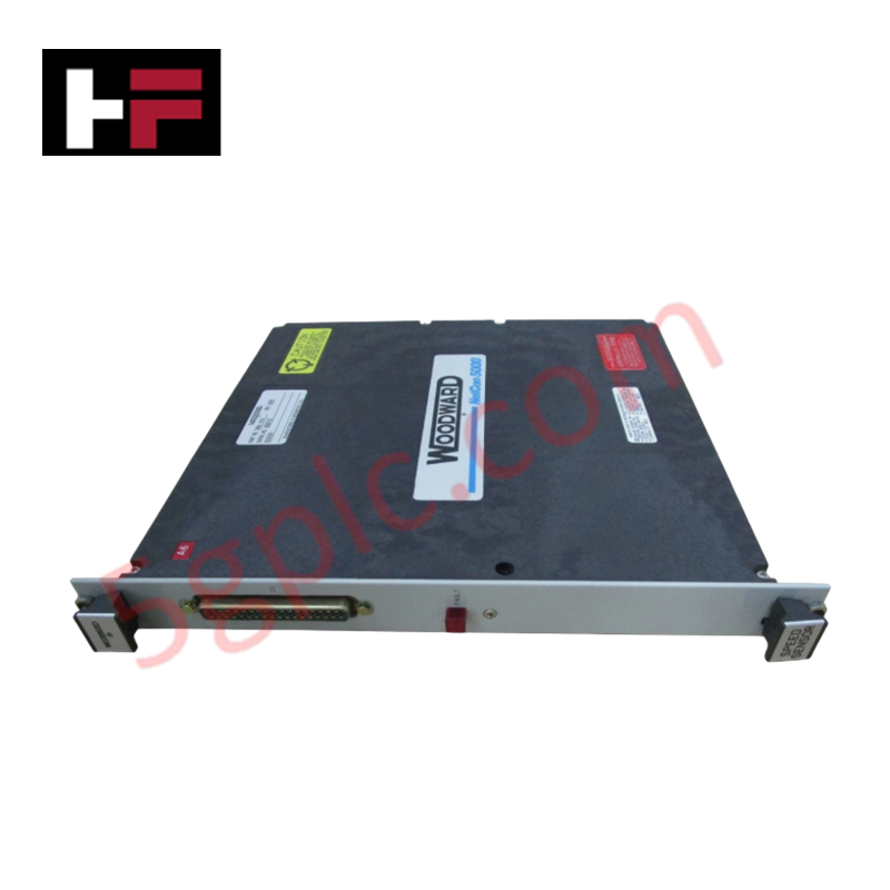
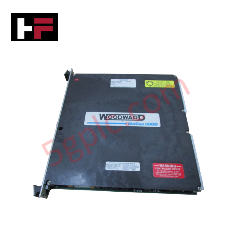
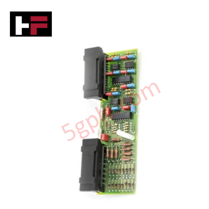
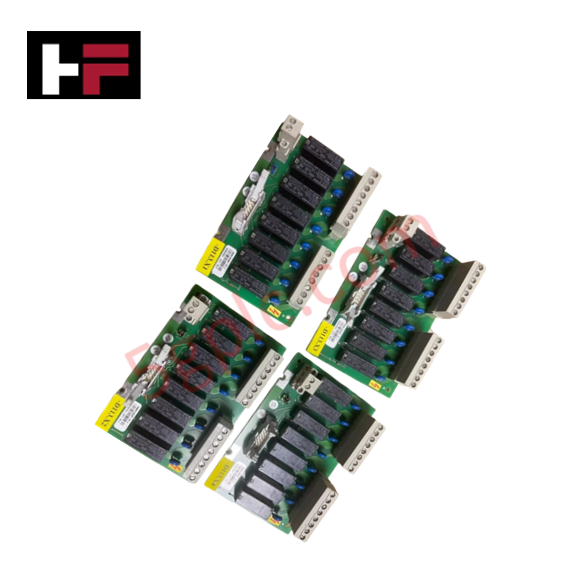
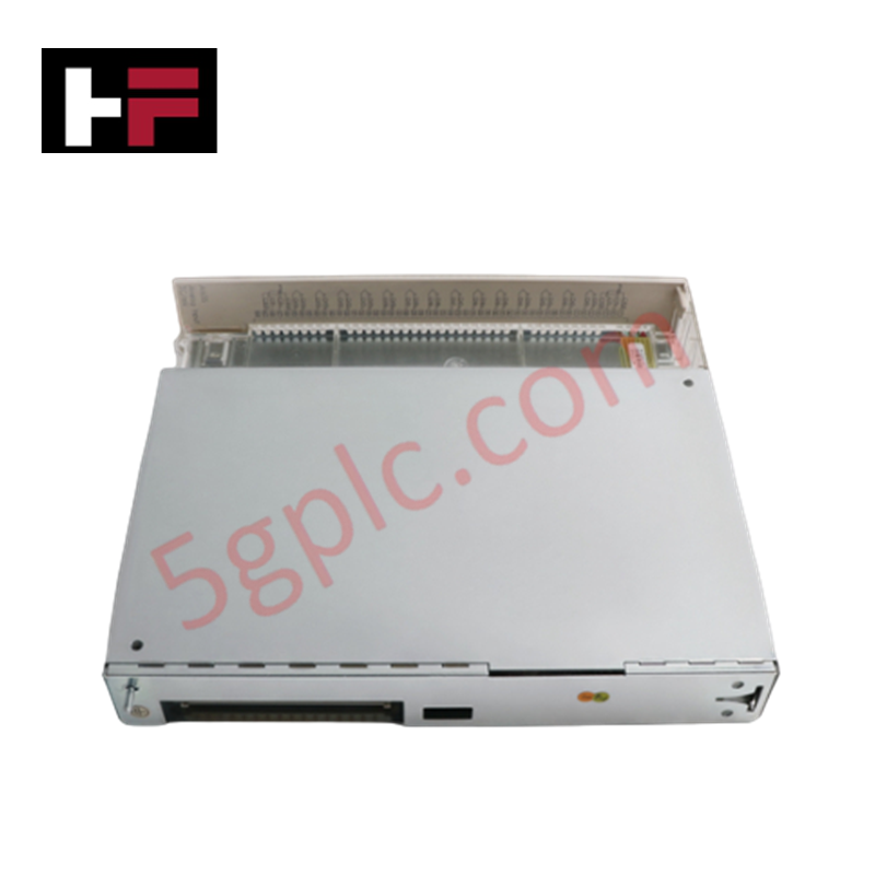
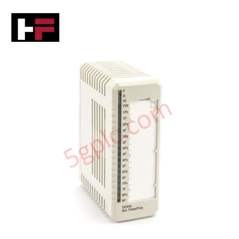
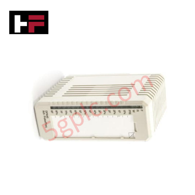
Configured for discrete control execution in MicroNet systems, the Woodward 5464-654 (Discrete Output Module) provides direct electrical execution of relay driver signals to interface with Woodward Relay Modules.
Hardware Specifications
| Parameter | Specification |
|---|---|
| Model | 5464-654 |
| Brand | Woodward |
| Origin | USA |
| Channels | 32 |
| Update Time | 5 ms |
Actuator Loop Feedback Response and Thermal Heat Sink Dissipation Profiles
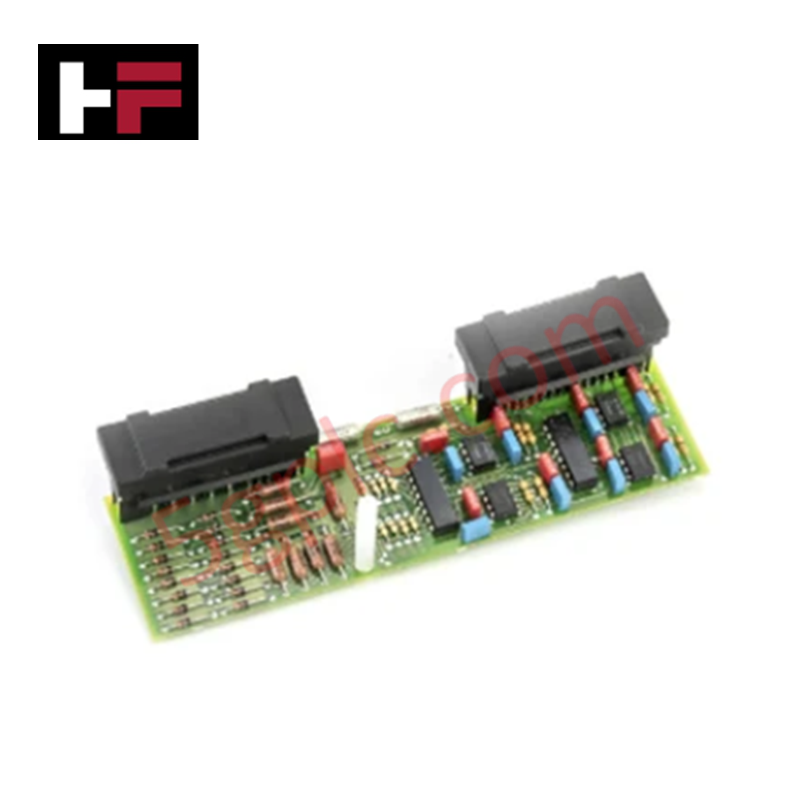
The 5464-654 module processes digital data received from the CPU to generate non-isolated relay driver signals. The interface relies on a daisy-chained, low-density discrete cable configuration to communicate with external relay modules. To ensure consistent actuator loop feedback response, the module update time is fixed at 5 ms. In the event of a CPU communication loss, all outputs are transitioned to the off state to prevent unintended actuation. While the module itself does not require calibration or potentiometer adjustments, the external relay stage requires a stable, independent 24 VDC power source to ensure proper operation of the field-connected contacts. Thermal management within the chassis is maintained through standard card guide airflow; ensure the motherboard connection is secure to support the thermal heat sink dissipation profiles of the internal logic components.
Frequently Asked Questions
Q: Does the 5464-654 module provide galvanic isolation for the field outputs?
A: No. The relay driver signals generated by this module are non-isolated. All isolation is provided by the external Woodward Relay Modules to which this board interfaces.
Q: Is it possible to perform a hot-swap replacement of this module?
A: The module is designed to be disengaged from the motherboard via front-panel toggles; however, ensure the CPU has been placed in a maintenance state or the system power is managed according to facility safety protocols before physical removal, as the module controls live field outputs.
Field Installation Guidelines
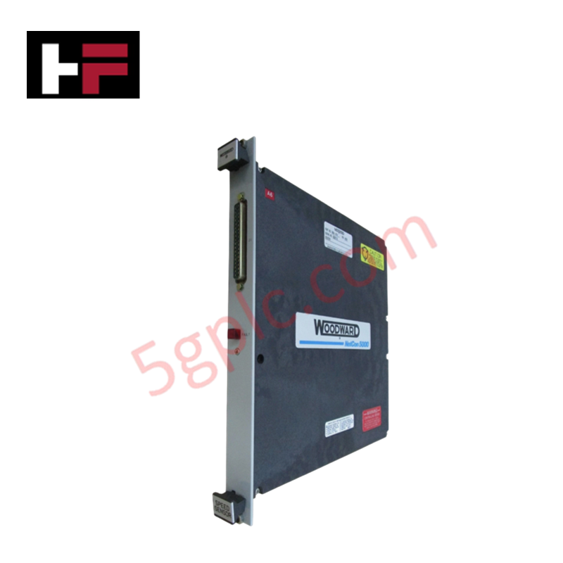
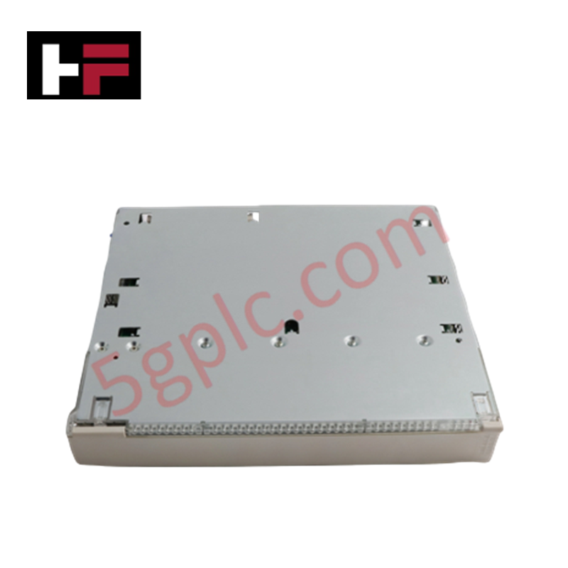
- Insertion: Slide the module into the designated control chassis card guides. Ensure both top and bottom motherboard connectors are fully seated before tightening the front panel retaining screws.
- Cabling: Connect the module to the primary Relay Module using a low-density discrete cable. If daisy-chaining to a second module, use a second low-density cable from the first relay module to the subsequent unit.
- Powering: Provide a separate 24 VDC power source for the external relay contacts. Verify that the power supply current capacity is sufficient for the total relay load across all channels.
- Retention: Utilize the two front-panel toggles for safe disengagement; do not force the module out of the guides without first toggling the handles to disengage the backplane connectors.
Additional Information
- 100% Genuine Parts: All products are original and authentic, ensuring reliable industrial performance.
- 30-Day Refund Guarantee: Return any in-stock item within 30 days in original, unopened packaging for a full refund (excluding shipping and fees).
- 12-Month Warranty: Covers defects in materials or workmanship; excludes misuse, normal wear, or unauthorized modifications.
- Worldwide Shipping: We ship via USPS, UPS, FedEx, and DHL. Delivery times vary by country and may be subject to customs or import fees.
- Support & Contact: Technical and warranty assistance is available anytime. Contact us here: Contact.
- Purchase Guidance: Check product specifications and compatibility carefully before ordering to ensure proper application.
Tech & Buying Guide

Understanding Dry Contacts in PLC Wiring: An Industrial Automation Guide
Mastering contact switching principles is essential for reliable control panels. Field devices and PLCs interface through dry or wet contacts. This technical guide examines the mechanics of dry contacts, explores their wiring architectures, and evaluates their key advantages in industrial automation.

Ultimate Commissioning Checklist for Industrial Automation Systems: An Engineering Guide
Commissioning is the most decisive phase of an industrial automation project, transforming control hardware and software into an operational facility. Thorough testing prevents costly startup delays and builds customer confidence. This guide covers essential checklists, electrical standards, and best practices.

Redundant Automation Systems: Core Architecture, Business Value, and Technical Advantages
Unplanned downtime poses a major financial threat to process manufacturing. To prevent costly interruptions, engineers deploy redundant PLC and DCS architectures that ensure continuous operation when hardware fails. This technical guide explores redundancy principles, critical system nodes, and real-world scenarios.