


Product Details
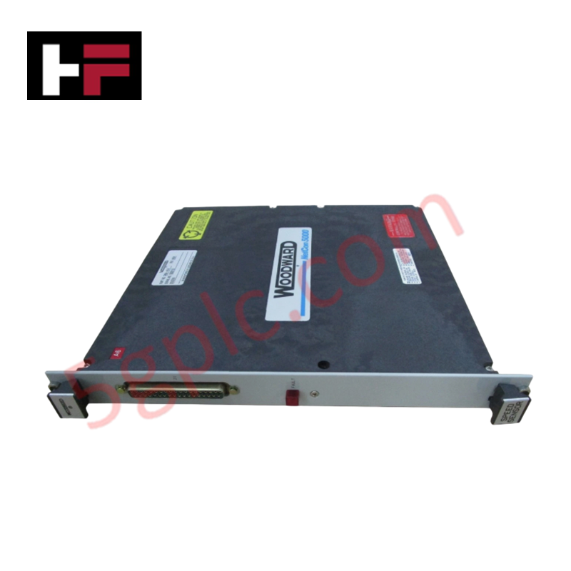
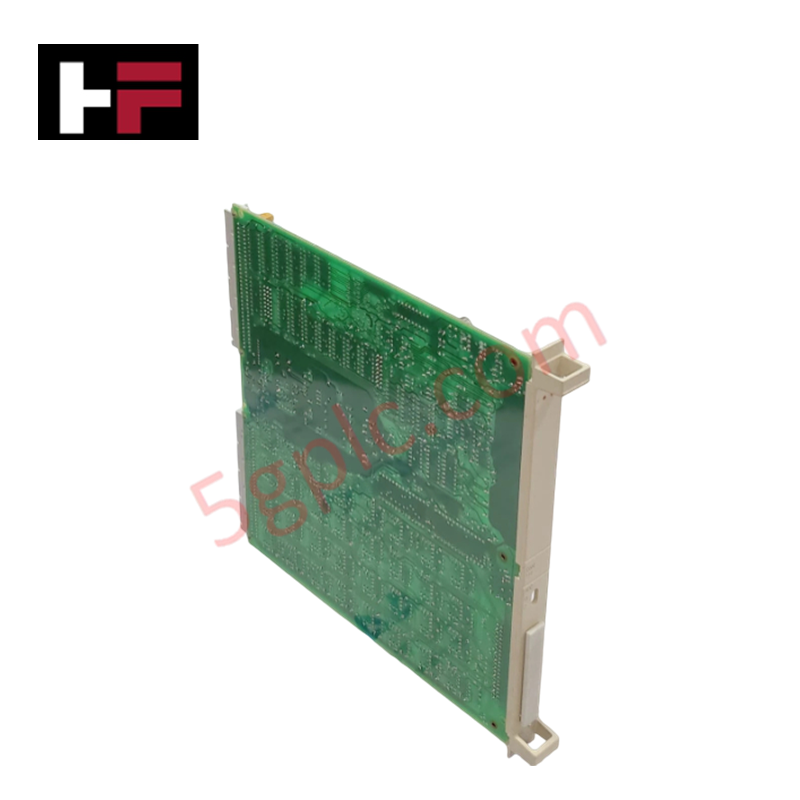
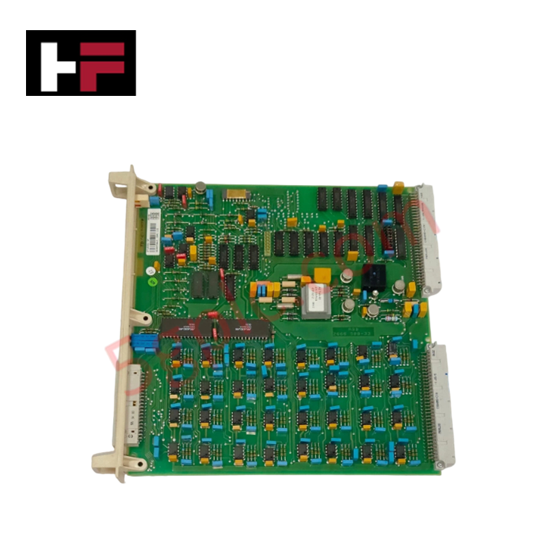
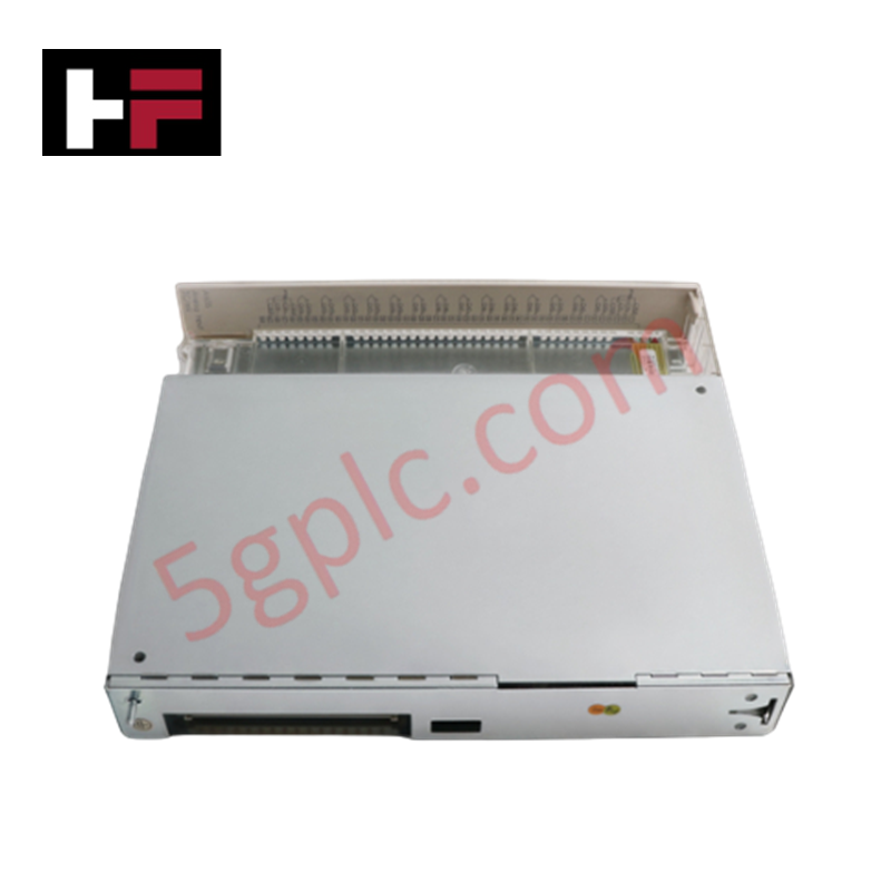
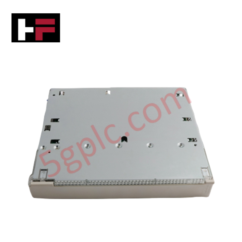
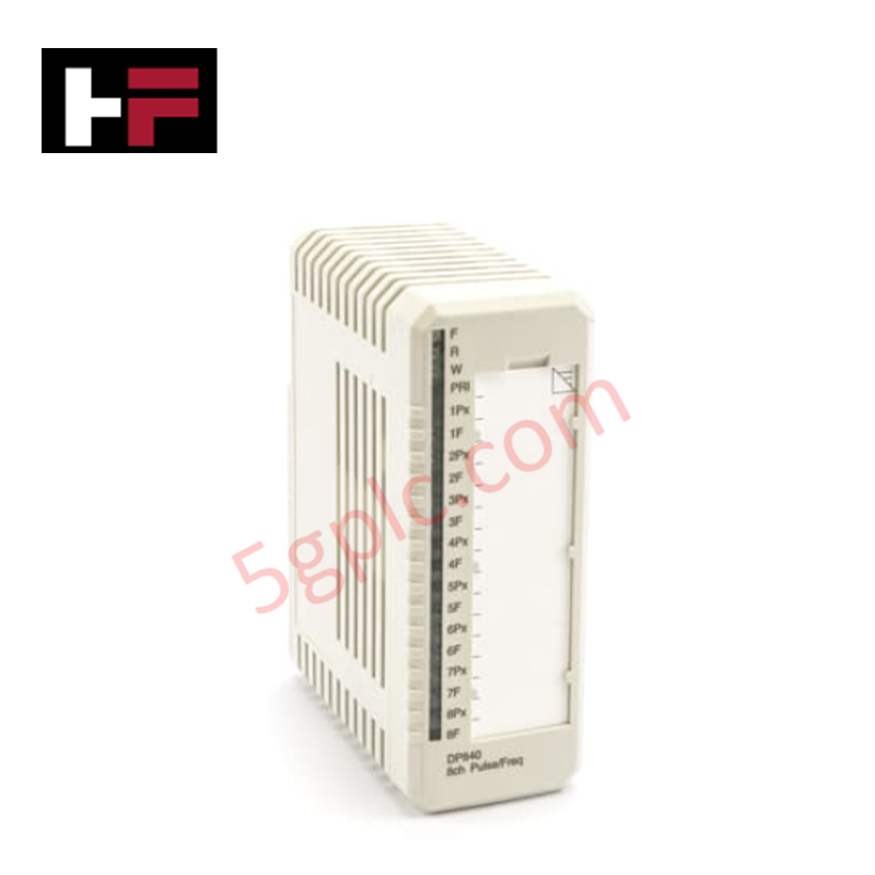
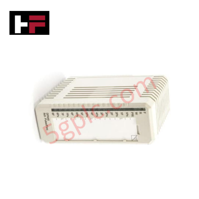
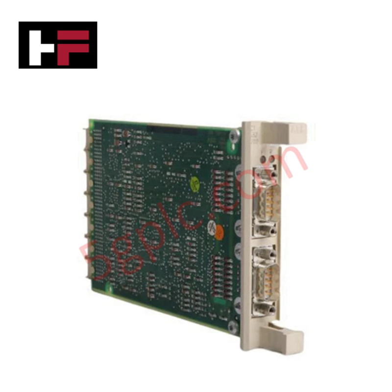
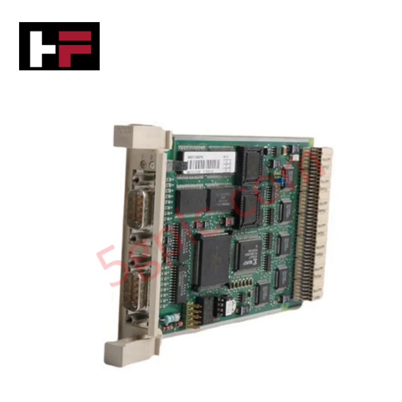
Configured for rotational speed monitoring in industrial governor platforms, the Woodward 5464-414 (5464-414 Digital Micro Processor Speed Sensor) provides direct physical/electrical execution of frequency-to-digital signal conversion.
Hardware Specifications
| Parameter | Specification |
|---|---|
| Model | 5464-414 |
| Brand | Woodward |
| Origin | USA |
| Weight | 0.96 kg |
| Dimensions | 2.6 x 24.8 x 26.2 cm |
| Input Types | Pulse train, analog, digital |
| Output Types | Digital and analog signals |
Actuator Loop Feedback Response
The 5464-414 utilizes digital signal processing to convert mechanical rotation into actionable data for governing control loops. By providing precise frequency-based feedback, the module enables the connected controller to maintain a stable actuator loop feedback response. The conversion latency of the internal microprocessor is optimized to minimize phase shift, ensuring that the governor can respond effectively to transient load fluctuations without introducing oscillatory behavior into the fuel control system.
Frequently Asked Questions
Q: Does the 5464-414 require specific shielding for input signal cables?
A: Yes, due to the nature of pulse train and low-level analog speed inputs, use shielded twisted-pair cabling. The shield must be terminated at the control system ground point to minimize induced electromagnetic noise.
Q: Is this module field-configurable for different input signal ranges?
A: The module supports various input types, including pulse trains and analog signals. Configuration should be performed via the associated Woodward controller's software interface to match the sensor's pulse-per-revolution (PPR) count and signal voltage levels.
Field Installation Guidelines
- Mounting: Secure the module within a vibration-dampened cabinet. Ensure the 2.6 x 24.8 x 26.2 cm chassis is oriented to facilitate airflow around the electronics.
- Wiring: Separate signal lines from high-current AC output or drive lines to prevent induced electrical noise from corrupting the speed data.
- Grounding: Establish a low-impedance ground connection to the module chassis. Verify the integrity of the connection to the common system reference point.
- Validation: During commissioning, verify the input frequency against a secondary tachometer reading to confirm the accuracy of the digital pulse conversion before enabling closed-loop governor control.
Additional Information
- 100% Genuine Parts: All products are original and authentic, ensuring reliable industrial performance.
- 30-Day Refund Guarantee: Return any in-stock item within 30 days in original, unopened packaging for a full refund (excluding shipping and fees).
- 12-Month Warranty: Covers defects in materials or workmanship; excludes misuse, normal wear, or unauthorized modifications.
- Worldwide Shipping: We ship via USPS, UPS, FedEx, and DHL. Delivery times vary by country and may be subject to customs or import fees.
- Support & Contact: Technical and warranty assistance is available anytime. Contact us here: Contact.
- Purchase Guidance: Check product specifications and compatibility carefully before ordering to ensure proper application.
Tech & Buying Guide

Understanding Dry Contacts in PLC Wiring: An Industrial Automation Guide
Mastering contact switching principles is essential for reliable control panels. Field devices and PLCs interface through dry or wet contacts. This technical guide examines the mechanics of dry contacts, explores their wiring architectures, and evaluates their key advantages in industrial automation.

Ultimate Commissioning Checklist for Industrial Automation Systems: An Engineering Guide
Commissioning is the most decisive phase of an industrial automation project, transforming control hardware and software into an operational facility. Thorough testing prevents costly startup delays and builds customer confidence. This guide covers essential checklists, electrical standards, and best practices.

Redundant Automation Systems: Core Architecture, Business Value, and Technical Advantages
Unplanned downtime poses a major financial threat to process manufacturing. To prevent costly interruptions, engineers deploy redundant PLC and DCS architectures that ensure continuous operation when hardware fails. This technical guide explores redundancy principles, critical system nodes, and real-world scenarios.