


Product Details
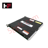
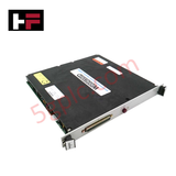
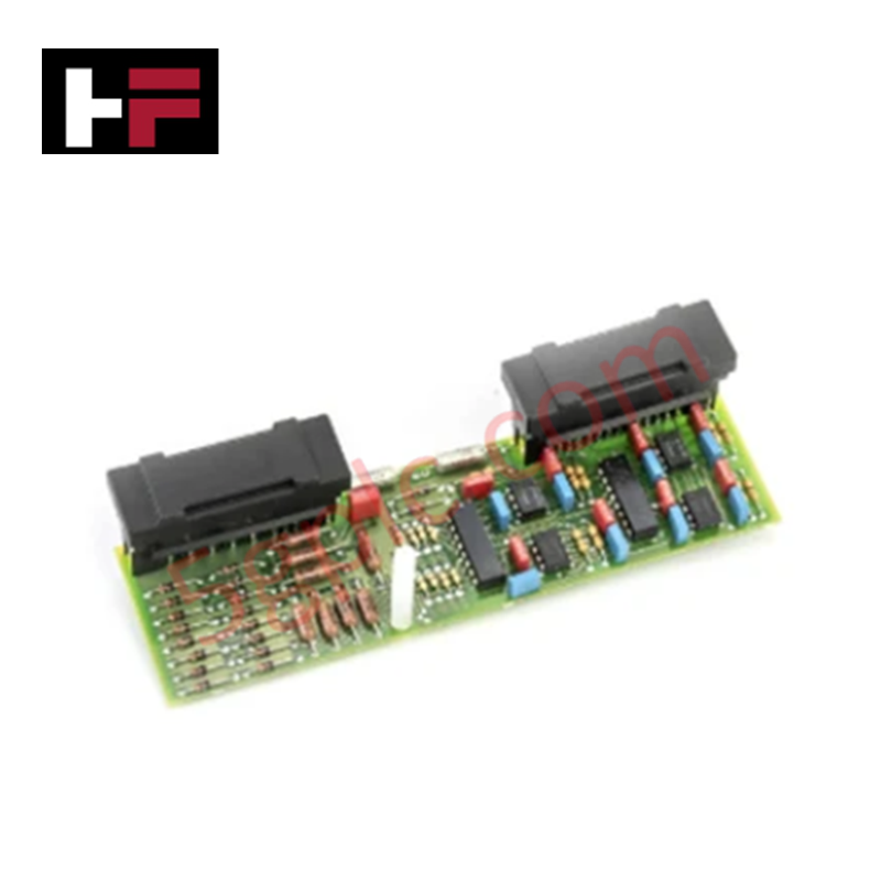
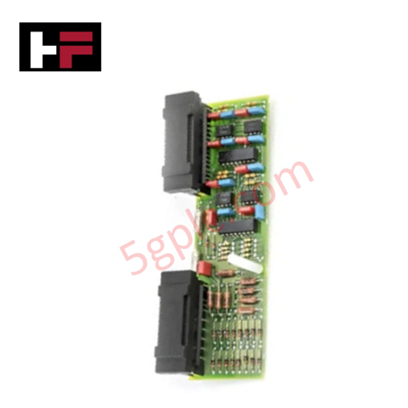
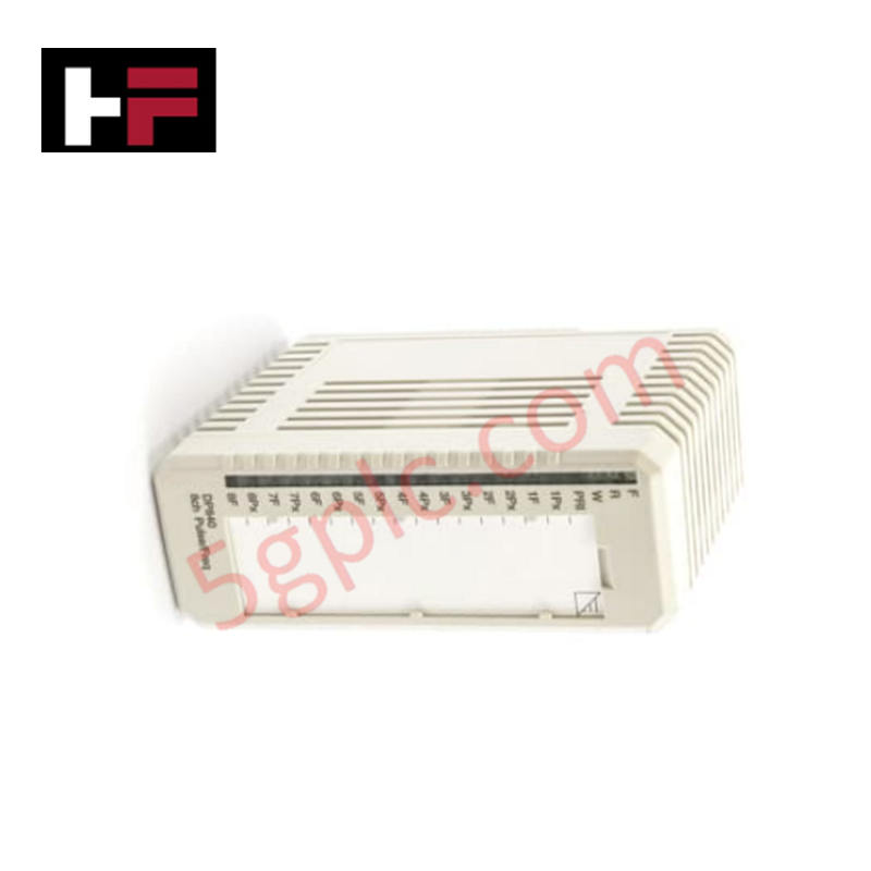
Configured for temperature sensor signal acquisition in control networks, the Woodward 5463-887 (5463-887 Thermocouple Input Module) provides direct physical execution of thermocouple signal conditioning, cold junction compensation (CJC), and digital conversion.
Hardware Specifications
| Parameter | Specification |
|---|---|
| Model | 5463-887 |
| Brand | Woodward |
| Origin | USA |
| Operating Temp | -40 deg C to +70 deg C |
| Power Consumption | Not specified |
| Function | Thermocouple Input |
Actuator Loop Feedback Response and Thermal Heat Sink Dissipation Profiles
The 5463-887 module interfaces with thermocouple sensors to measure thermal variables through the Seebeck effect. The onboard signal conditioning circuitry performs millivolt amplification and cold junction compensation (CJC) to derive accurate temperature readings. To maintain measurement stability in high-density industrial control enclosures, the module housing utilizes thermal heat sink dissipation profiles, preventing localized thermal drift that could impact CJC accuracy. The module maintains signal fidelity and limits noise injection, which is required to support precise actuator loop feedback response when used in thermal process control or turbine governor management. Each channel incorporates galvanic isolation to mitigate common-mode interference, ensuring data integrity in electrically noisy environments.
Frequently Asked Questions
Q: Is the cold junction compensation (CJC) feature automated for all supported thermocouple types?
A: Yes, the module provides automated CJC to account for the temperature differential at the thermocouple connection terminals. Ensure that thermocouple wires are connected directly to the module terminal blocks to maintain accurate reference temperature tracking.
Q: Can this module be hot-swapped while the system is powered?
A: No. Removing or inserting the module while the system bus is energized may cause transient signals or communication faults on the backplane. De-energize the controller rack prior to any physical module maintenance.
Field Installation Guidelines
- Mounting: Install the module in the designated rack slot, ensuring the connector pins are properly aligned with the backplane bus. Fasten the module securely to the rack chassis to ensure robust thermal contact and grounding.
- Wiring: Use thermocouple-grade extension wire that matches the sensor type (e.g., K, J, T). Avoid splicing wires; if necessary, utilize terminal blocks of the same material as the thermocouple wire to prevent secondary thermocouple junctions.
- Shielding: Terminate the cable shield at the designated cabinet ground point. Ensure the shield does not contact the process housing to prevent ground loops that interfere with low-level signal measurement.
- Validation: After installation, verify the input reading against a calibrated temperature reference. Check the diagnostic status via the control system software to confirm the module is reporting healthy loop status.
Additional Information
- 100% Genuine Parts: All products are original and authentic, ensuring reliable industrial performance.
- 30-Day Refund Guarantee: Return any in-stock item within 30 days in original, unopened packaging for a full refund (excluding shipping and fees).
- 12-Month Warranty: Covers defects in materials or workmanship; excludes misuse, normal wear, or unauthorized modifications.
- Worldwide Shipping: We ship via USPS, UPS, FedEx, and DHL. Delivery times vary by country and may be subject to customs or import fees.
- Support & Contact: Technical and warranty assistance is available anytime. Contact us here: Contact.
- Purchase Guidance: Check product specifications and compatibility carefully before ordering to ensure proper application.
Tech & Buying Guide

Understanding Dry Contacts in PLC Wiring: An Industrial Automation Guide
Mastering contact switching principles is essential for reliable control panels. Field devices and PLCs interface through dry or wet contacts. This technical guide examines the mechanics of dry contacts, explores their wiring architectures, and evaluates their key advantages in industrial automation.

Ultimate Commissioning Checklist for Industrial Automation Systems: An Engineering Guide
Commissioning is the most decisive phase of an industrial automation project, transforming control hardware and software into an operational facility. Thorough testing prevents costly startup delays and builds customer confidence. This guide covers essential checklists, electrical standards, and best practices.

Redundant Automation Systems: Core Architecture, Business Value, and Technical Advantages
Unplanned downtime poses a major financial threat to process manufacturing. To prevent costly interruptions, engineers deploy redundant PLC and DCS architectures that ensure continuous operation when hardware fails. This technical guide explores redundancy principles, critical system nodes, and real-world scenarios.