


Product Details
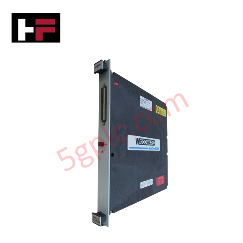
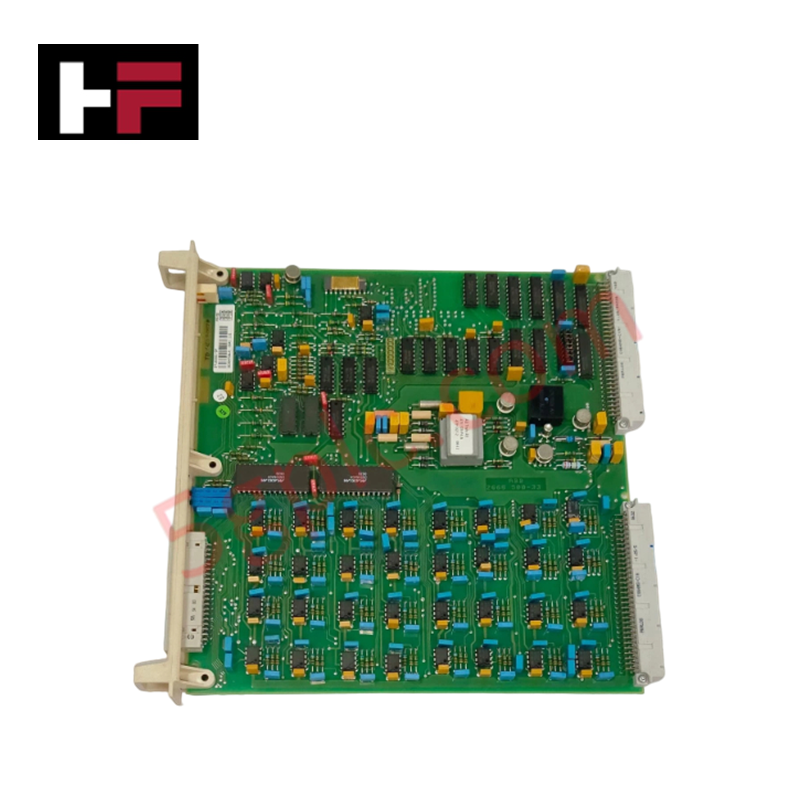
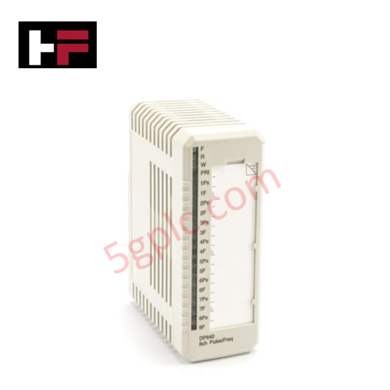
Configured for precision signal conditioning in industrial control systems, the Woodward 5463-785 (5463-785 Analog Input Module) provides direct electrical execution of isolated analog data acquisition.
Hardware Specifications
| Parameter | Specification |
|---|---|
| Model | 5463-785 |
| Brand | Woodward |
| Origin | USA |
| Weight | 0.3 kg |
| Dimensions | 19.1 cm x 2.5 cm x 23.5 cm |
| Operating Temp | -40 deg C to +70 deg C |
| Power Consumption | 0.6 A (maximum) at 24 VDC |
| Channel Isolation | Yes |
Harmonic Distortion Suppression and Signal Integrity
The 5463-785 module incorporates channel-to-channel galvanic isolation to mitigate ground loops and electromagnetic interference common in high-density control cabinets. The module is engineered for compatibility with standard 4-20 mA current loops, ensuring compatibility with industrial sensors and transmitters. By providing electrical isolation, the unit ensures harmonic distortion suppression, maintaining signal fidelity in environments with high-frequency noise or significant power-line harmonics. Proper thermal heat sink dissipation profiles should be considered when mounting the module in enclosures with high power-density components to ensure long-term operation within the specified temperature range.
Frequently Asked Questions
Q: Does the 5463-785 module support hot-swapping while the host controller is powered?
A: No. The module is not designed for hot-swapping. All power must be removed from the module and the backplane prior to insertion or removal to prevent potential damage to the pins or sensitive input circuitry.
Q: How is the channel isolation maintained in high-noise environments?
A: Isolation is maintained via onboard galvanic barriers that electrically decouple the input sensing stage from the backplane communication logic. To ensure this protection remains effective, the signal shield must be terminated at the designated common point provided on the module terminal block.
Field Installation Guidelines
- Mounting: Ensure the module is securely seated in the rack to guarantee proper contact with the backplane connectors.
- Wiring: Use shielded, twisted-pair cabling for all 4-20 mA analog inputs. Route these cables away from high-voltage AC lines and VFD output cables to minimize induced interference.
- Grounding: Terminate cable shields at the module or system reference point as indicated in the system wiring diagrams to maintain the integrity of the galvanic isolation.
- Environment: While the module is rated for -40 deg C to +70 deg C, avoid mounting the unit directly above high-heat sources to maximize the service life of the internal components.
Additional Information
- 100% Genuine Parts: All products are original and authentic, ensuring reliable industrial performance.
- 30-Day Refund Guarantee: Return any in-stock item within 30 days in original, unopened packaging for a full refund (excluding shipping and fees).
- 12-Month Warranty: Covers defects in materials or workmanship; excludes misuse, normal wear, or unauthorized modifications.
- Worldwide Shipping: We ship via USPS, UPS, FedEx, and DHL. Delivery times vary by country and may be subject to customs or import fees.
- Support & Contact: Technical and warranty assistance is available anytime. Contact us here: Contact.
- Purchase Guidance: Check product specifications and compatibility carefully before ordering to ensure proper application.

Tech & Buying Guide

Understanding Dry Contacts in PLC Wiring: An Industrial Automation Guide
Mastering contact switching principles is essential for reliable control panels. Field devices and PLCs interface through dry or wet contacts. This technical guide examines the mechanics of dry contacts, explores their wiring architectures, and evaluates their key advantages in industrial automation.

Ultimate Commissioning Checklist for Industrial Automation Systems: An Engineering Guide
Commissioning is the most decisive phase of an industrial automation project, transforming control hardware and software into an operational facility. Thorough testing prevents costly startup delays and builds customer confidence. This guide covers essential checklists, electrical standards, and best practices.

Redundant Automation Systems: Core Architecture, Business Value, and Technical Advantages
Unplanned downtime poses a major financial threat to process manufacturing. To prevent costly interruptions, engineers deploy redundant PLC and DCS architectures that ensure continuous operation when hardware fails. This technical guide explores redundancy principles, critical system nodes, and real-world scenarios.