










Product Details
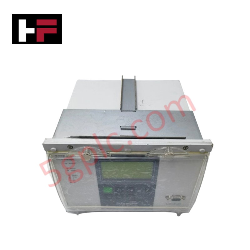
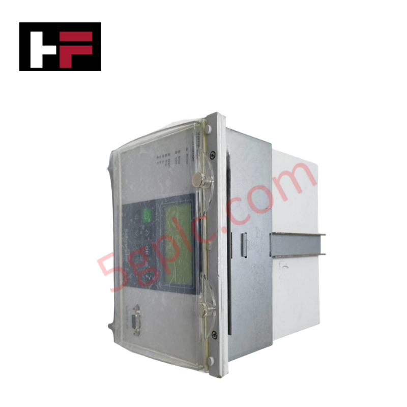
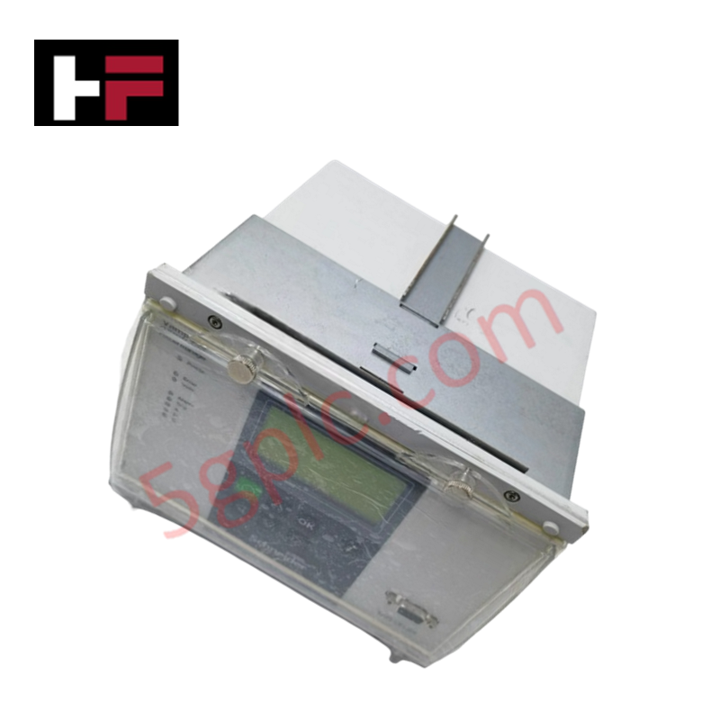
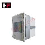
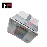
The Schneider Electric V255-073749, also cataloged as the V255-073749 Feeder and Motor Protection Relay, operates as a dedicated hardware component for selective current monitoring and automated breaker trip execution within industrial power distribution networks. It samples phase vector magnitudes to isolate electrical anomalies directly at the hardware layer.
Hardware Specifications
| Parameter | Specification |
|---|---|
| Model | V255-073749 |
| Brand | Schneider Electric |
| Origin | Finland |
| Weight | 0.3 kg (0.66 lbs) |
| Dimensions | 12.0 cm x 10.5 cm x 13.0 cm |
| Operating Temp | -10 to +55 deg C standard industrial limits |
| Power Consumption | Standard auxiliary operational load |
| Series | VAMP 255 |
| Product Type | Protection Relays |
| Mounting Type | Flush panel mounting configuration |
| Protection Functions | Overcurrent, Earth Fault, Motor, Capacitor Bank, and Busbar Protection |
Profinet / EtherNet/IP Deterministic Networks and I/O Density Scaling
The VAMP 255 platform executes real-time telemetry streaming over deterministic Profinet and EtherNet/IP networks to synchronize power quality data with process controllers. The internal processing core scales hardware sampling density across current inputs, maintaining deterministic scanning speed without delaying critical overcurrent trip decisions. Firmware flash compatibility ensures fault-event records and setting matrices remain intact during system power cycles.
Frequently Asked Questions
Q: What panel preparation is required for the flush mount enclosure?
A: Cut a rectangular panel cutout corresponding to the 12.0 cm x 10.5 cm x 13.0 cm physical dimensions, ensuring adequate rear clearance for terminal block wiring and grounding straps.
Q: How does the processing core maintain coordination with downstream circuit breakers?
A: The onboard micro-controller samples high-density current vectors continuously. Trip logic runs locally on the hardware matrix to initiate contact closure in milliseconds, bypassing network transfer delays.
Q: What primary equipment functions can be assigned to the protective channels?
A: The relay logic can be configured to protect feeder lines, electric motors, capacitor banks, and distribution busbars against earth faults and overcurrent conditions.
Field Installation Guidelines
- Cut the designated mounting opening on the enclosure door and insert the relay from the front face.
- Secure the flush-mounting brackets from the rear of the panel, tightening the retaining screws evenly to prevent panel distortion.
- Connect the protective earth (PE) ground terminal directly to the central panel earth bus using a short, high-strand copper conductor.
- Route phase CT secondary wiring to the dedicated rear terminal blocks, verifying correct current transformer polarity before energizing.
- Terminate auxiliary power and communication lines in separate wire channels away from high-voltage current measurement leads.
- Verify terminal screw tightness across all active contact blocks prior to applying control power.
Additional Information
- 100% Genuine Parts: All products are original and authentic, ensuring reliable industrial performance.
- 30-Day Refund Guarantee: Return any in-stock item within 30 days in original, unopened packaging for a full refund (excluding shipping and fees).
- 12-Month Warranty: Covers defects in materials or workmanship; excludes misuse, normal wear, or unauthorized modifications.
- Worldwide Shipping: We ship via USPS, UPS, FedEx, and DHL. Delivery times vary by country and may be subject to customs or import fees.
- Support & Contact: Technical and warranty assistance is available anytime. Contact us here: Contact.
- Purchase Guidance: Check product specifications and compatibility carefully before ordering to ensure proper application.


Tech & Buying Guide

Demystifying the DDE Protocol in Legacy Industrial Automation Systems
Modern control systems rely heavily on seamless interprocess communication to exchange operational data between software programs. Microsoft first introduced the Dynamic Data Exchange (DDE) protocol in 1987 to enable real-time data sharing. In factory automation, DDE served as an early bridge between control software and Windows desktop applications. Therefore, understanding DDE mechanics provides crucial insights into how legacy industrial networks established software-level connectivity.

Demystifying CPU Communication Ports in Siemens PLC Architectures
Industrial automation relies heavily on robust data exchange between devices. Without seamless connectivity, field instruments, network switches, human-machine interfaces, and programmable logic controllers cannot coordinate effectively. Therefore, understanding the various CPU communication ports available in Siemens hardware ensures efficient factory automation design and seamless system integration.

Mastering the Siemens PLC Scan Cycle: How the CPU Executes Automation Programs
Industrial automation relies heavily on programmable logic controllers (PLCs) to manage complex manufacturing processes. Many engineers dive straight into programming without mastering the underlying architecture. However, understanding how a PLC CPU executes a program ensures reliable system design. Therefore, mastering the scan cycle optimizes both performance and troubleshooting in modern control systems.