


Product Details
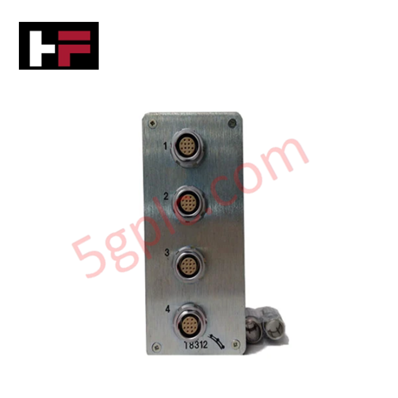
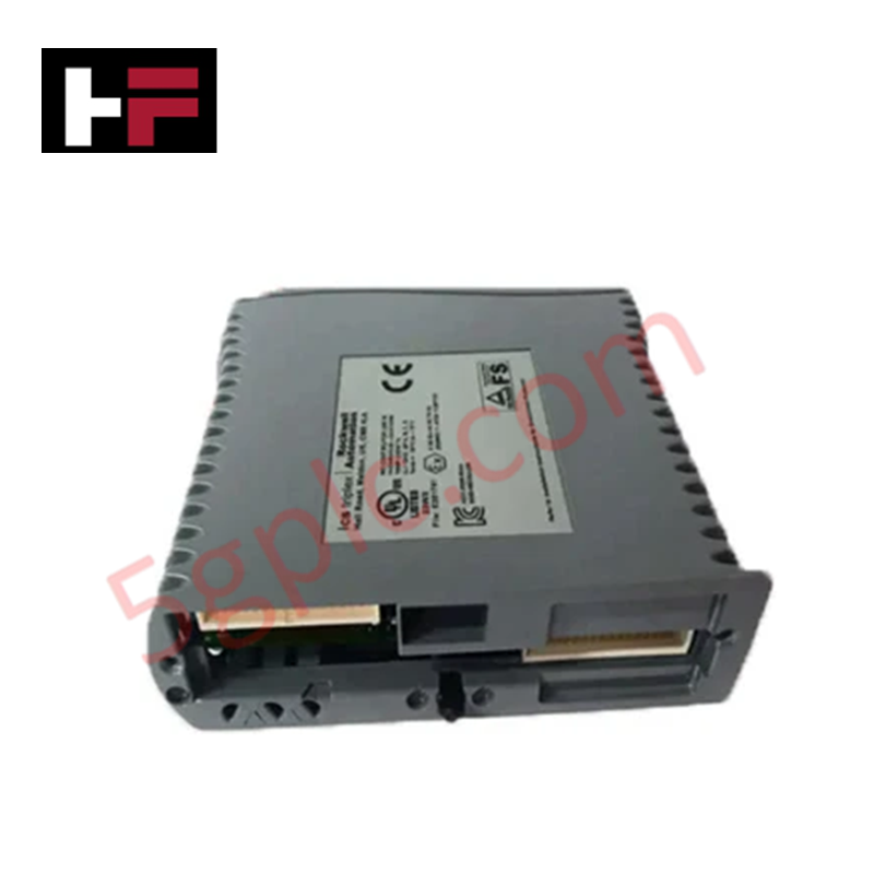
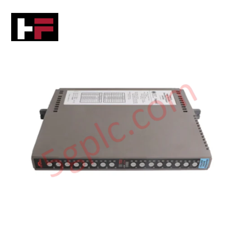
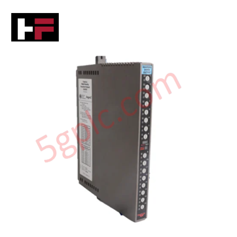
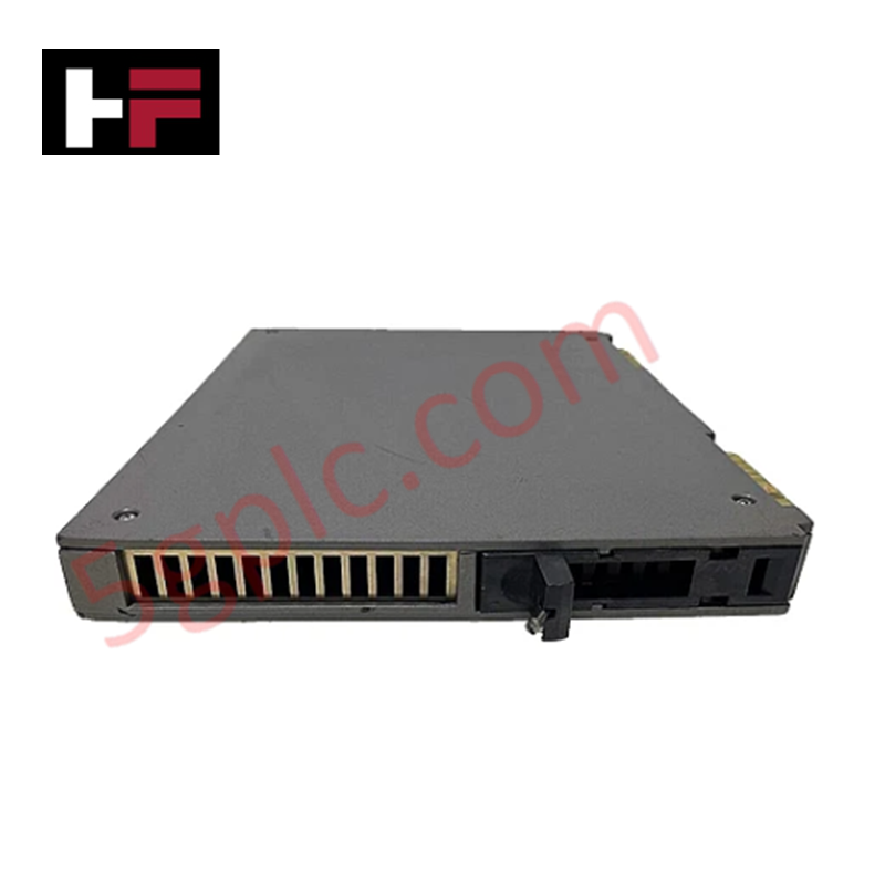
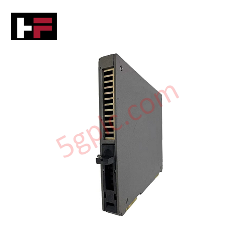
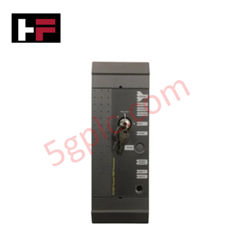
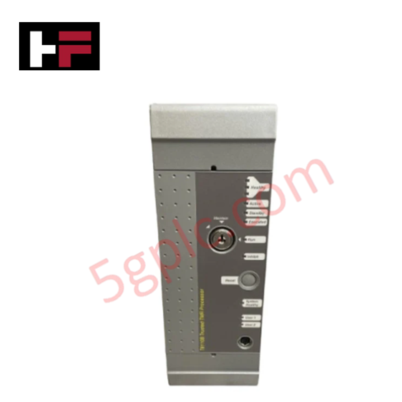
Configured for high-speed I/O expansion in Trusted TMR control networks, the ICS Triplex T8312-4C (T8312-4C Expander Interface Adaptor) provides direct physical and electrical execution. The module serves as a deterministic communication bridge, facilitating the synchronization and exchange of data between the primary controller chassis and remote 7-way expander configurations.
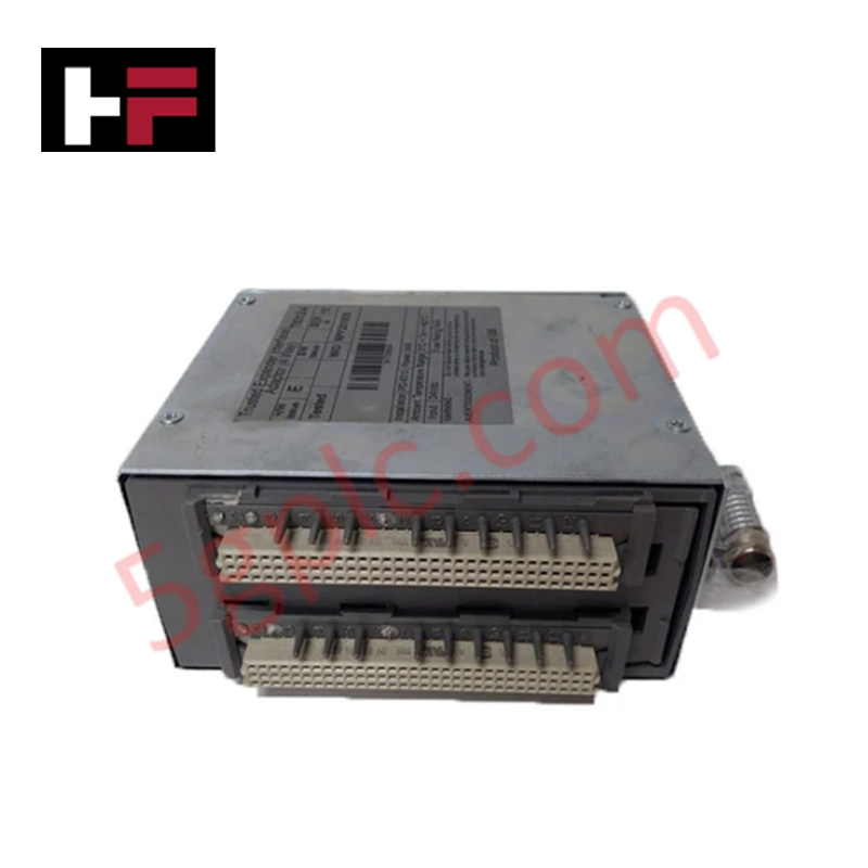
Hardware Specifications
| Parameter | Specification |
|---|---|
| Model | T8312-4C |
| Brand | ICS Triplex |
| Origin | USA |
| Weight | 1 kg |
| Dimensions | 30 cm x 20 cm x 25 cm |
| Operating Temp | Standard Industrial |
| Power Consumption | Configuration Dependent |
| Interface Capacity | 7-way Expander Support |
SIS Triple Modular Redundancy (TMR) Architecture
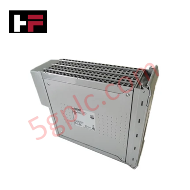
The T8312-4C integrates into the triple modular redundancy (TMR) 2oo3 architecture to facilitate fail-safe state execution across distributed I/O racks. The module maintains synchronized communication paths, ensuring that all data processed across the expander bus is validated by internal voting logic. Galvanic isolation is implemented at the backplane interface to protect internal processing circuits from field-side electrical interference. This ensures that any single-point failure within the communication link is masked, preserving the deterministic nature of the safety control loop.
Frequently Asked Questions
Q: Does the T8312-4C support hot-swapping during active system operation?
A: The T8312-4C supports hot-swapping within the Trusted TMR backplane. Before module extraction, the system must be placed in a controlled maintenance state for the specific expander node to prevent spurious safety trips resulting from the interruption of synchronized communication.
Q: How is the 7-way expansion mapping configured within the system?
A: Expansion mapping is configured via the engineering workstation software, which defines the address range for each of the seven expander chassis. The T8312-4C adaptor automatically aligns with these assignments upon power-up, provided the backplane addressing is correctly initialized.
Field Installation Guidelines
- Ensure the chassis backplane is powered down before seating the T8312-4C into the target slot to avoid connector arcing.
- Confirm that the module is fully aligned with the backplane guides before applying force to engage the connector pins.
- Tighten front-panel fasteners to ensure consistent structural ground contact, which is necessary for optimal electromagnetic compatibility.
- Route all interconnecting communication cabling through shielded conduits, ensuring shield continuity at the cabinet entrance to mitigate potential interference.
- Perform a diagnostic loop test post-installation to verify that the expander interface is successfully communicating with the primary controller and all 7-way nodes are reporting status.
Additional Information
- 100% Genuine Parts: All products are original and authentic, ensuring reliable industrial performance.
- 30-Day Refund Guarantee: Return any in-stock item within 30 days in original, unopened packaging for a full refund (excluding shipping and fees).
- 12-Month Warranty: Covers defects in materials or workmanship; excludes misuse, normal wear, or unauthorized modifications.
- Worldwide Shipping: We ship via USPS, UPS, FedEx, and DHL. Delivery times vary by country and may be subject to customs or import fees.
- Support & Contact: Technical and warranty assistance is available anytime. Contact us here: Contact.
- Purchase Guidance: Check product specifications and compatibility carefully before ordering to ensure proper application.


Tech & Buying Guide

Essential Motion Control Commands: A Practical Guide for Engineers
Automation engineers often rely on precise position and speed control to drive modern factory machinery. Modern industrial systems, such as Programmable Logic Controllers (PLCs) and Distributed Control Systems (DCS), depend heavily on standardized motion instructions. Mastering these commands ensures operational safety, protects mechanical components, and optimizes cycle times across production lines.

The Role of Intrinsic Safety Barriers in PLC and DCS Architectures
Implementing robust protection in hazardous industrial environments represents a fundamental safety requirement in factory automation. Process facilities often handle volatile gases, dusts, and chemical agents that pose significant combustion risks. Consequently, control system engineers must deploy energy-limiting interfaces to isolate safe-area control cabinets from hazardous-area field instrumentation. This article examines the function, selection, and electrical principles of intrinsic safety barriers within modern PLC and DCS networks.

Architectural Selection and Scale Classification of PLC Systems in Industrial Automation
Selecting the correct control platform represents a foundational engineering decision in factory automation. System designers must carefully balance technical parameters against long-term operational requirements when implementing a Programmable Logic Controller (PLC). This article examines the critical evaluation metrics, physical scale classifications, and operational architectures of modern control systems.