











Product Details
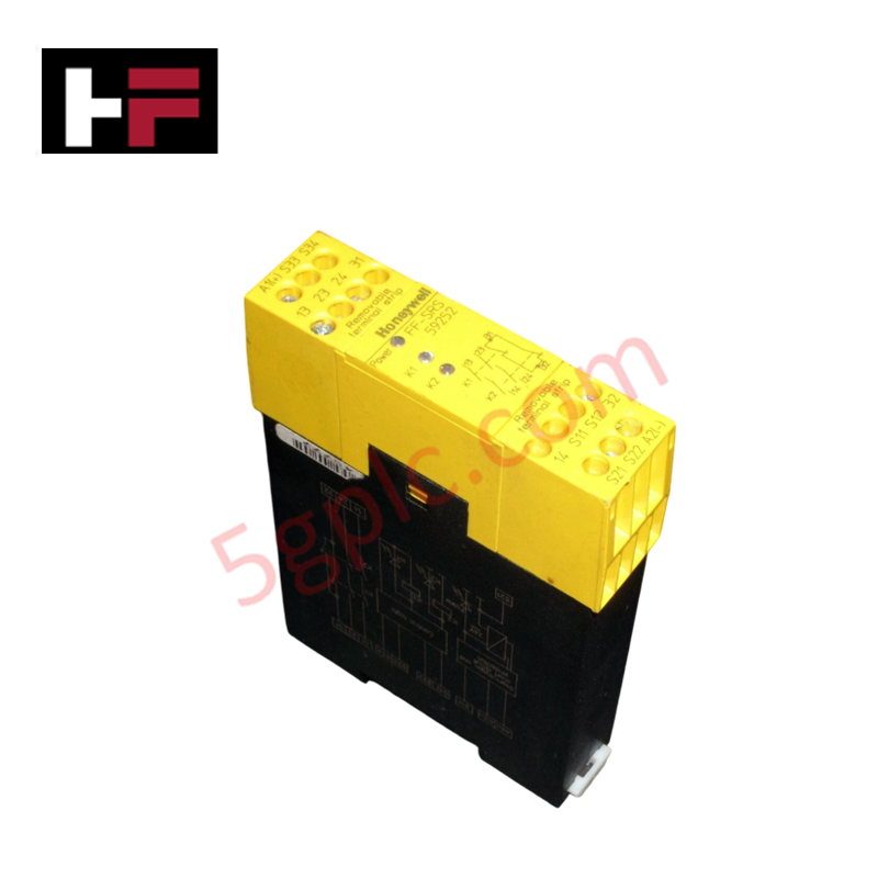
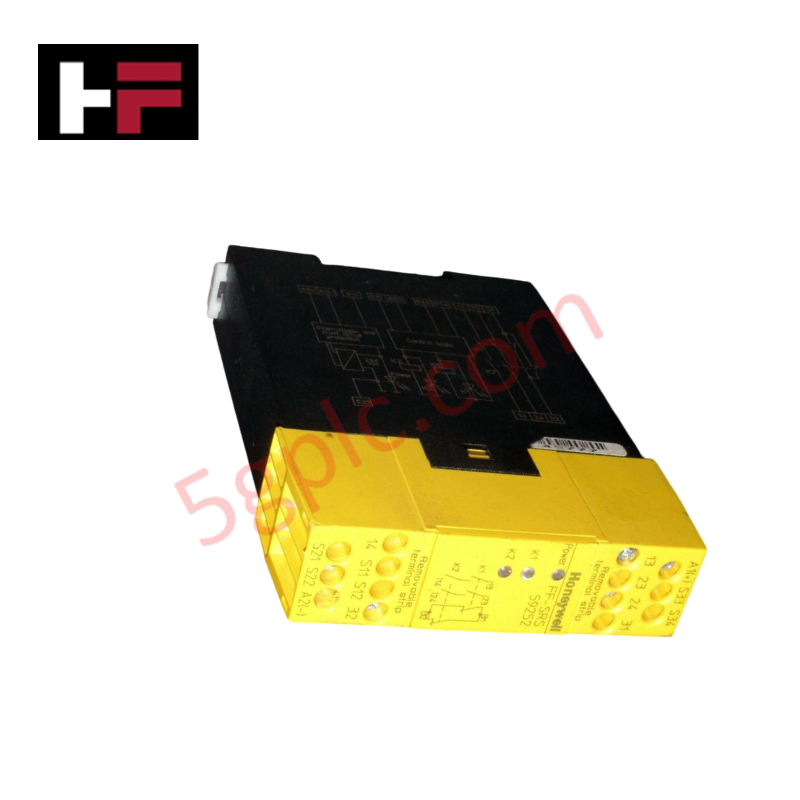
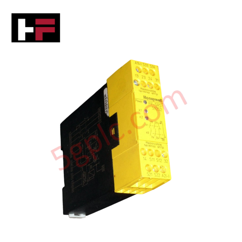
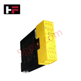
The Honeywell FF-SRS59252, also cataloged as the FF-SRS59252 Safety Controller, operates as a dedicated hardware component for dual-channel emergency stop signal monitoring and safety circuit interruption within industrial safety instrumentation systems. Operating on a 24 VAC control voltage supply, the module monitors dual-channel switch contacts to execute immediate power isolation upon emergency stop actuation. The internal relay logic provides force-guided switching contacts that prevent unsafe restart sequences during contact weld or channel fault conditions.
Hardware Specifications
| Parameter | Specification |
|---|---|
| Model | FF-SRS59252 |
| Brand | Honeywell |
| Origin | USA |
| Weight | 0.49 lbs (0.22 kg) |
| Dimensions | Standard DIN-Rail Safety Relay Housing |
| Operating Temp | -10 to 55 deg C |
| Power Consumption | Passive Logic / 24 VAC Control Circuit |
| Operating Voltage | 24 VAC |
| Logic Architecture | Dual Channel Monitoring |
| Mounting Type | 35 mm DIN-Rail Mount |
| Product Category | Emergency Stop Safety Module |
Channel-to-Channel Isolation
The FF-SRS59252 safety module implements full galvanic channel-to-channel isolation between independent input circuits and internal control logic relays. Internal isolation barriers prevent electrical cross-talk, short circuits, or stray voltage transients from propagating across dual emergency stop channels. This isolated channel design guarantees that a single contact fault or line short on one monitoring channel is detected instantly by the diagnostics without compromising the safety shutdown function of the secondary loop.
Frequently Asked Questions
Q: How does the dual-channel input logic respond if a single contact fails to open during an emergency stop command?
A: The module detects channel imbalance during trip activation, latches the output relays in a safe de-energized state, and prevents a system reset until the fault is cleared.
Q: What is the primary functional requirement for supplying control power to the 24 VAC terminals?
A: Control power must originate from a dedicated Class 2 isolated safety transformer to preserve overall system galvanic isolation standards.
Q: Can the output switching contacts be used directly to break high-current motor loads?
A: No, output safety contacts must drive interposing safety contactors or circuit breakers rated for the specific load current and inductive switching profile.
Field Installation Guidelines
- Mount the module vertically onto a standard 35 mm DIN-rail inside an IP54-rated protective enclosure.
- Verify that supply power across the control terminals remains strictly at 24 VAC prior to energizing the circuit.
- Wire emergency stop pushbuttons using separate multi-conductor shielded cables for Channel 1 and Channel 2 to eliminate cross-channel short circuits.
- Connect overall cable shields to the enclosure frame grounding terminal using a low-impedance connection.
- Perform a full functional trip test and channel cross-fault check before restoring operational power to downstream machinery.
Additional Information
- 100% Genuine Parts: All products are original and authentic, ensuring reliable industrial performance.
- 30-Day Refund Guarantee: Return any in-stock item within 30 days in original, unopened packaging for a full refund (excluding shipping and fees).
- 12-Month Warranty: Covers defects in materials or workmanship; excludes misuse, normal wear, or unauthorized modifications.
- Worldwide Shipping: We ship via USPS, UPS, FedEx, and DHL. Delivery times vary by country and may be subject to customs or import fees.
- Support & Contact: Technical and warranty assistance is available anytime. Contact us here: Contact.
- Purchase Guidance: Check product specifications and compatibility carefully before ordering to ensure proper application.




Tech & Buying Guide

Demystifying Open Platform Communication (OPC): The Backbone of Industrial Interoperability
Interoperability remains a cornerstone requirement for modern smart factories and process automation. Open Platform Communication (OPC) bridges the gap between disparate hardware platforms, control systems, and visualization software. By establishing a universal communication standard, OPC allows field controllers, SCADA platforms, and enterprise software from different vendors to exchange real-time data seamlessly.

Understanding Siemens PLC Memory Cards: MMC, SMC, and SD Solutions in Industrial Automation
Memory management plays a pivotal role in maintaining control system reliability across modern manufacturing plants. Industrial control systems rely on specialized memory cards to store project logic, firmware updates, and retentive system data. Siemens uses several memory architectures, including Micro Memory Cards (MMC) and SIMATIC Memory Cards (SMC). Engineers must understand these hardware variations to ensure zero data loss and minimize downtime during maintenance routines.

Redefining Control Systems: The Rise of Flexible I/O Modules in Industrial Automation
Conventional input-output architectures often limit engineering agility and inflate long-term inventory costs. Today, Flexible Input/Output Modules (FIOM) are transforming how control system engineers design, commission, and maintain automation infrastructure. By allowing individual channel software configuration, FIOM technology bridges the gap between rigid hardware design and dynamic plant requirements.