










Product Details
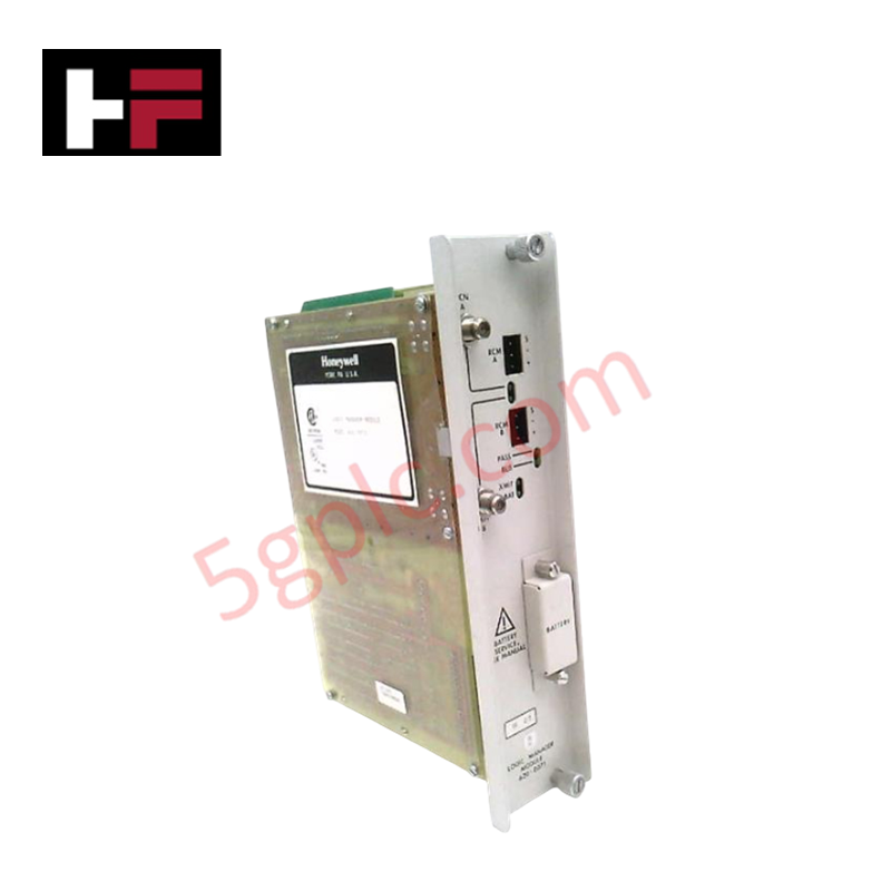
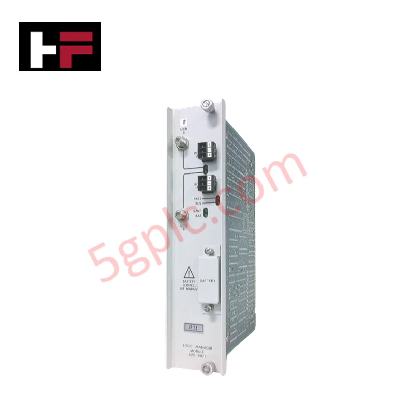
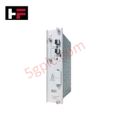
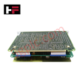
The Honeywell 620-0071 serves as the primary 620 Logic Manager Module utilized to execute discrete logic processing tasks across Honeywell programmable logic controller platforms. The PC board component processes digital input and output states directly via the system chassis backplane interface, managing user-configured instruction sets without external communications latency.
Hardware Specifications
| Parameter | Specification |
|---|---|
| Model | 620-0071 |
| Brand | Honeywell |
| Origin | USA |
| Weight | 2.60 lbs |
| Dimensions | Standard IPC/620 Rack Slot Footprint |
| Operating Temp | 0 to 60 deg C |
| Power Consumption | Backplane Load Dependent |
| Category | PLCs/Machine Control (PLC Module/Rack) |
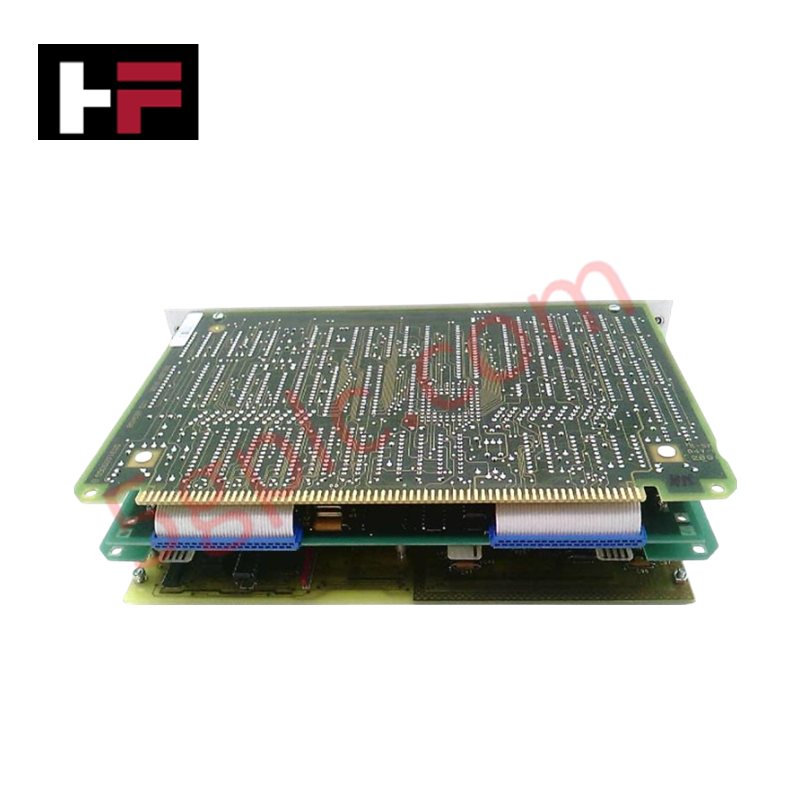
| Construction | Printed Circuit Board Assembly |
Honeywell Deterministic Networks & Firmware Flash Compatibility
The logic manager module utilizes integrated communications logic to sync with local rack I/O density scaling profiles. Backplane bus operations maintain strict deterministic timing constraints, preventing cycle-time degradation during complex instruction execution. The physical logic memory architecture supports direct binary operation processing, matching standardized firmware configurations validated for the Honeywell IPC/620 series platforms.
Frequently Asked Questions
Q: Does the 620-0071 module support live hot-swap insertion within an energized rack?
A: No. Standard engineering guidelines for this legacy series dictate that the rack frame must be entirely de-energized before inserting or extracting the logic board to avoid transient bus corruption or electrical pin damage.
Q: How is the execution status monitored on this hardware assembly?
A: The module relies on host backplane interface flags and onboard physical status indicators to report active logic runtime execution states and detect system bus synchronization errors.
Field Installation Guidelines
- Completely disconnect all primary power supplies to the target PLC rack housing before attempting physical installation or board removal.
- Align the board assembly vertically along the standard chassis slot track guides, pushing smoothly until the rear connectors fully engage with the backplane pin matrix.
- Tighten all integrated faceplate retention fasteners to eliminate the risk of intermittent board alignment issues caused by ambient plant vibrations.
- Verify all field wiring shields are correctly terminated at the designated low-impedance grounding bar within the local panel enclosure.
Additional Information
- 100% Genuine Parts: All products are original and authentic, ensuring reliable industrial performance.
- 30-Day Refund Guarantee: Return any in-stock item within 30 days in original, unopened packaging for a full refund (excluding shipping and fees).
- 12-Month Warranty: Covers defects in materials or workmanship; excludes misuse, normal wear, or unauthorized modifications.
- Worldwide Shipping: We ship via USPS, UPS, FedEx, and DHL. Delivery times vary by country and may be subject to customs or import fees.
- Support & Contact: Technical and warranty assistance is available anytime. Contact us here: Contact.
- Purchase Guidance: Check product specifications and compatibility carefully before ordering to ensure proper application.




Tech & Buying Guide

Demystifying CPU Communication Ports in Siemens PLC Architectures
Industrial automation relies heavily on robust data exchange between devices. Without seamless connectivity, field instruments, network switches, human-machine interfaces, and programmable logic controllers cannot coordinate effectively. Therefore, understanding the various CPU communication ports available in Siemens hardware ensures efficient factory automation design and seamless system integration.

Mastering the Siemens PLC Scan Cycle: How the CPU Executes Automation Programs
Industrial automation relies heavily on programmable logic controllers (PLCs) to manage complex manufacturing processes. Many engineers dive straight into programming without mastering the underlying architecture. However, understanding how a PLC CPU executes a program ensures reliable system design. Therefore, mastering the scan cycle optimizes both performance and troubleshooting in modern control systems.

How to Connect to Siemens S7 PLCs: 5 Essential Communication Methods
Establishing a reliable hardware link between a programming terminal and a Siemens SIMATIC controller is essential for engineering workflows. Field engineers rely on distinct physical layers, ranging from legacy serial connections to high-speed Industrial Ethernet protocols. Modern factory automation environments prioritize fast data transfer and seamless driver integration. Selecting the correct connection method simplifies program downloads, online monitoring, and system troubleshooting in complex control systems.