












Product Details
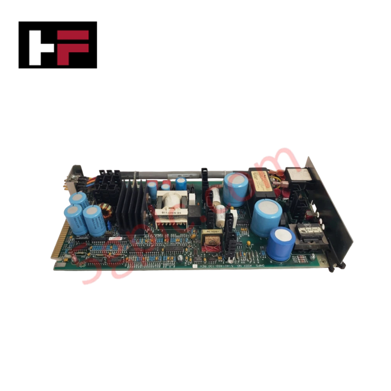
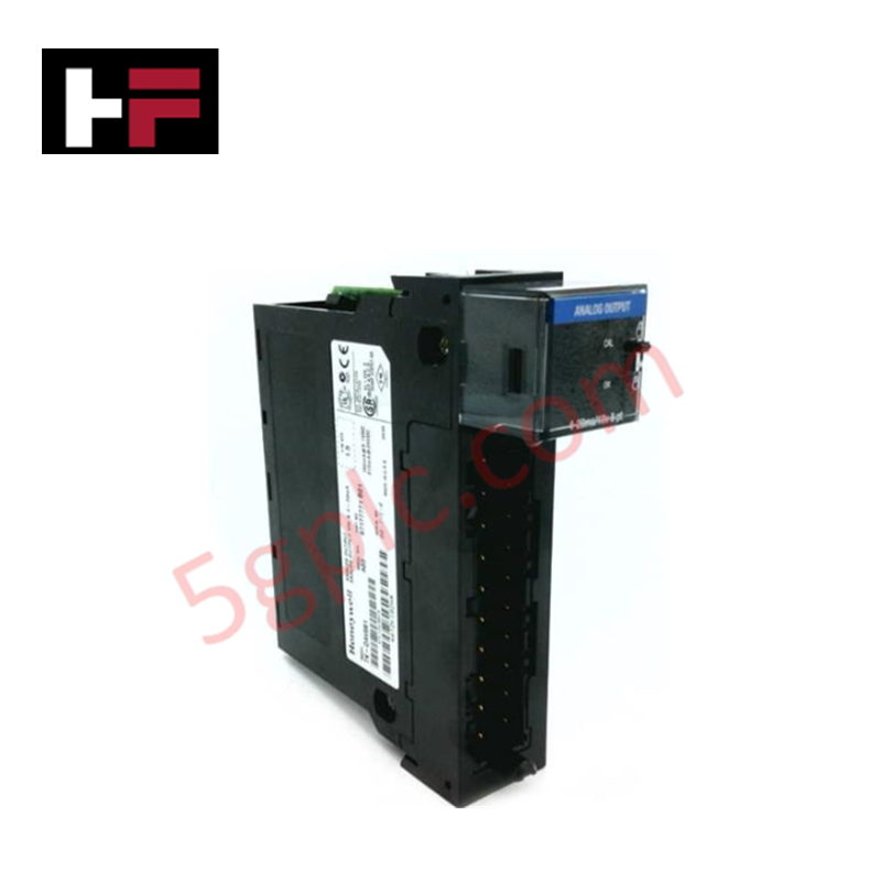
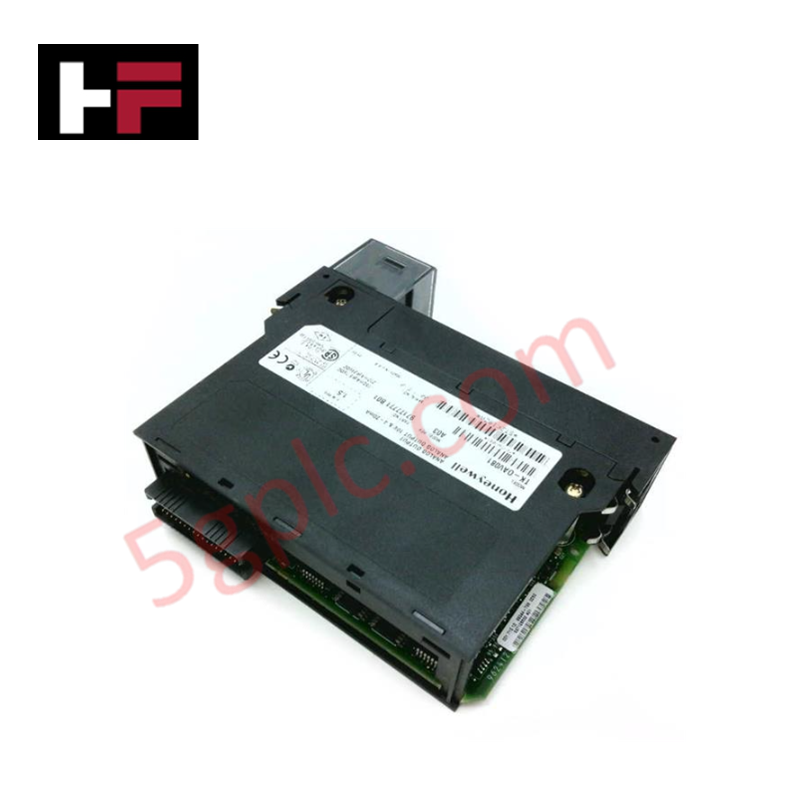
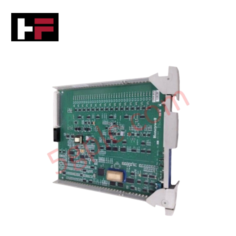
The Honeywell 51401497-100, also cataloged as the 51401469-100 Power Supply Module, operates as a dedicated hardware component for dual-node power distribution within Honeywell TDC 3000 LCN systems.
Hardware Specifications
| Parameter | Specification |
|---|---|
| Model | 51401497-100 (PCB Assembly 51401469-100) |
| Brand | Honeywell |
| Origin | USA |
| Weight | ~4.8 lbs |
| Operating Temp | 0 to 60 deg C |
| Power Consumption | Dual-node supply, load-dependent |
| Primary Output | Regulated DC power for two independent control nodes |
| Circuit Protection | Over-voltage protection, anti-interference filtering |
| Hardware Adjustment | Three-position voltage margin switch (High, Normal, Low) |
| System Compatibility | Honeywell TDC 3000 / LCN Architecture |
4-20 mA HART Loop Protocol & Channel Isolation
The module regulates internal DC distribution rails across the system rack to supply secondary power to rack-mounted I/O cards and field bus transceivers. To protect sensitive downstream I/O loops, the internal power channels maintain channel-to-channel isolation and low-noise output regulation. This isolates primary 4-20 mA HART loop protocol signaling circuits from DC bus ripples and power supply switching transients, allowing transparent diagnostic transmission and field instrument telemetry.
Frequently Asked Questions
Q: Is live hot-swapping permitted for the 51401497-100 power supply module?
A: Hot-swapping under active load is not recommended due to power interruption risks on both dependent control nodes.
Q: How does the integrated voltage margin switch function on the assembly?
A: The three-position switch (High, Normal, Low) alters the regulated output voltage levels to perform stress testing and voltage tolerance validation on connected node cards.
Field Installation Guidelines
- Isolate main AC/DC power sources feeding the chassis frame prior to mounting or unseating the power module.
- Inspect chassis guide tracks and clean backplane connector pins of any particulate debris before insertion.
- Slide the power module card into the chassis slot, using the ejection handles to fully seat the PCB edge connectors into the rear socket.
- Confirm the voltage margin switch is locked in the "Normal" operational position prior to re-energizing the system.
- Secure all panel locking screws to establish frame ground connection and facilitate passive convection cooling across the housing.
Additional Information
- 100% Genuine Parts: All products are original and authentic, ensuring reliable industrial performance.
- 30-Day Refund Guarantee: Return any in-stock item within 30 days in original, unopened packaging for a full refund (excluding shipping and fees).
- 12-Month Warranty: Covers defects in materials or workmanship; excludes misuse, normal wear, or unauthorized modifications.
- Worldwide Shipping: We ship via USPS, UPS, FedEx, and DHL. Delivery times vary by country and may be subject to customs or import fees.
- Support & Contact: Technical and warranty assistance is available anytime. Contact us here: Contact.
- Purchase Guidance: Check product specifications and compatibility carefully before ordering to ensure proper application.



Tech & Buying Guide

Wellhead Control Panel (WHCP) Architecture in Oil and Gas Automation
Upstream oil and gas operations rely on specialized field control platforms to manage wellhead extraction safety and hydraulic actuation. A Wellhead Control Panel (WHCP) serves as a dedicated hydraulic and pneumatic power unit designed to operate critical Christmas Tree isolation valves. By interfacing field safety components directly with Programmable Logic Controller (PLC) architecture, a WHCP protects upstream extraction assets against overpressure, catastrophic leaks, and thermal emergencies.

Understanding Marshalling Cabinets in Industrial Control Systems Architecture
Industrial control system deployments rely on structured signal distribution to bridge field instrumentation with central processing hardware. A marshalling cabinet serves as the vital intermediate connection point between heavy field home-run multi-pair cables and delicate input/output (I/O) modules housed inside Programmable Logic Controller (PLC) or Distributed Control System (DCS) enclosures. By segregating field cable terminations from control hardware, engineers maintain system flexibility, safeguard controller components, and streamline commissioning workflows.

FAT vs SAT in Industrial Control Systems: Key Differences and Execution Guide
Industrial control system deployment relies on strict verification protocols to guarantee operational safety, system stability, and regulatory compliance. Commissioning complex Programmable Logic Controller (PLC) racks, Distributed Control Systems (DCS), and Safety Instrumented Systems (SIS) requires two critical milestones: the Factory Acceptance Test (FAT) and the Site Acceptance Test (SAT). Both procedures validate that system automation meets design specifications, but they occur at different stages of project execution and target distinct operational risks.