













Product Details
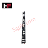
The Honeywell 51307186-275, also cataloged as the 51307186-275 Header Board, operates as a dedicated hardware component for signal routing and logic interface execution within Honeywell Experion PKS automation architectures. Interfacing directly with associated PWB 51307185-100 Rev.B base units, it utilizes 51454468 logic integration to route multi-channel field signals through specialized printed wiring board headers.
Hardware Specifications
| Parameter | Specification |
|---|---|
| Model | 51307186-275 (Rev.E) |
| Brand | Honeywell |
| Origin | China |
| Weight | 320 g (0.32 kg) |
| Dimensions | Standard Honeywell Header Board Dimensions |
| Operating Temp | 0 to 60 deg C |
| Power Consumption | Passive Logic Interface Board |
| Logic Type | 51454468 Logic Integration |
| Associated Board | PWB 51307185-100 Rev.B |
| Flame Rating | 94V-0 |
| Hazardous Ratings | Class I, Div. 2, Groups A-D, T4; Class I, Zone 2, AEx/Ex nA IIC T4 Gc; IECEx FMG 15.0038X; FM 15ATEX0065X |
Channel-to-Channel Isolation & DCS Process Telemetry
The 51307186-275 header board incorporates channel-to-channel isolation parameters to decouple field signals from system control logic paths. This shielding and isolation barrier prevents cross-talk and ground loop interference when routing 4-20 mA HART loop protocol signals across high-density interface headers. The board maintains signal scaling accuracy and deterministic loop behavior during process data transfer between field junction boxes and controller I/O modules operating in hazardous Zone 2 environments.
Frequently Asked Questions
Q: Does replacing a Rev.E 51307186-275 header board require modification of the host PWB 51307185-100 Rev.B base board?
A: No, the 51307186-275 Rev.E maintains physical pin arrangement and logic alignment with the PWB 51307185-100 Rev.B base unit for direct pin-header installation.
Q: Is hot-swapping supported for the 51307186-275 in Class I, Div. 2 environments?
A: No live swapping is permitted in hazardous locations unless the area is confirmed non-hazardous or power to the associated chassis and loop circuits has been fully isolated.
Field Installation Guidelines
- De-energize all system power sources and field loop wiring before installing or removing the header board.
- Align the header connectors of the 51307186-275 precisely with the mating pins on PWB 51307185-100 Rev.B to prevent pin bending.
- Observe ESD handling procedures by using an earth-grounded wrist strap during handling and installation.
- Verify that the enclosure installation complies with Class I, Div. 2 and Zone 2 safety standards, ensuring all cabinet seals remain intact.
Additional Information
- 100% Genuine Parts: All products are original and authentic, ensuring reliable industrial performance.
- 30-Day Refund Guarantee: Return any in-stock item within 30 days in original, unopened packaging for a full refund (excluding shipping and fees).
- 12-Month Warranty: Covers defects in materials or workmanship; excludes misuse, normal wear, or unauthorized modifications.
- Worldwide Shipping: We ship via USPS, UPS, FedEx, and DHL. Delivery times vary by country and may be subject to customs or import fees.
- Support & Contact: Technical and warranty assistance is available anytime. Contact us here: Contact.
- Purchase Guidance: Check product specifications and compatibility carefully before ordering to ensure proper application.




Tech & Buying Guide

Understanding Marshalling Cabinets in Industrial Control Systems Architecture
Industrial control system deployments rely on structured signal distribution to bridge field instrumentation with central processing hardware. A marshalling cabinet serves as the vital intermediate connection point between heavy field home-run multi-pair cables and delicate input/output (I/O) modules housed inside Programmable Logic Controller (PLC) or Distributed Control System (DCS) enclosures. By segregating field cable terminations from control hardware, engineers maintain system flexibility, safeguard controller components, and streamline commissioning workflows.

FAT vs SAT in Industrial Control Systems: Key Differences and Execution Guide
Industrial control system deployment relies on strict verification protocols to guarantee operational safety, system stability, and regulatory compliance. Commissioning complex Programmable Logic Controller (PLC) racks, Distributed Control Systems (DCS), and Safety Instrumented Systems (SIS) requires two critical milestones: the Factory Acceptance Test (FAT) and the Site Acceptance Test (SAT). Both procedures validate that system automation meets design specifications, but they occur at different stages of project execution and target distinct operational risks.

Hub vs Switch vs Router in Industrial Automation Architecture
Modern factory automation relies on reliable industrial networking infrastructure to exchange real-time field data across operational technology systems. Engineers often encounter networking hardware like hubs, switches, and routers when integrating Programmable Logic Controllers, Distributed Control Systems, and SCADA monitoring nodes. Although these devices share physical ports, they operate at different layers of the Open Systems Interconnection reference model and deliver distinct traffic management capabilities.