












Product Details
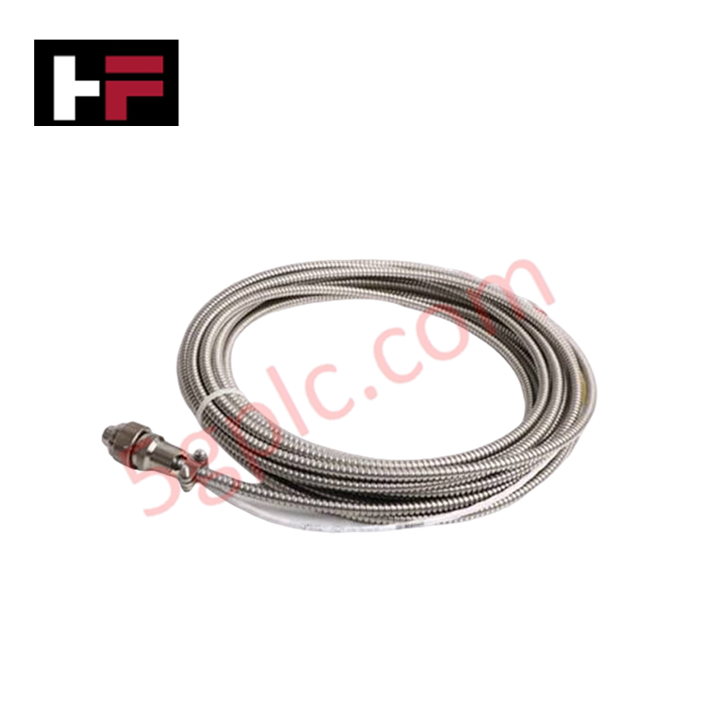
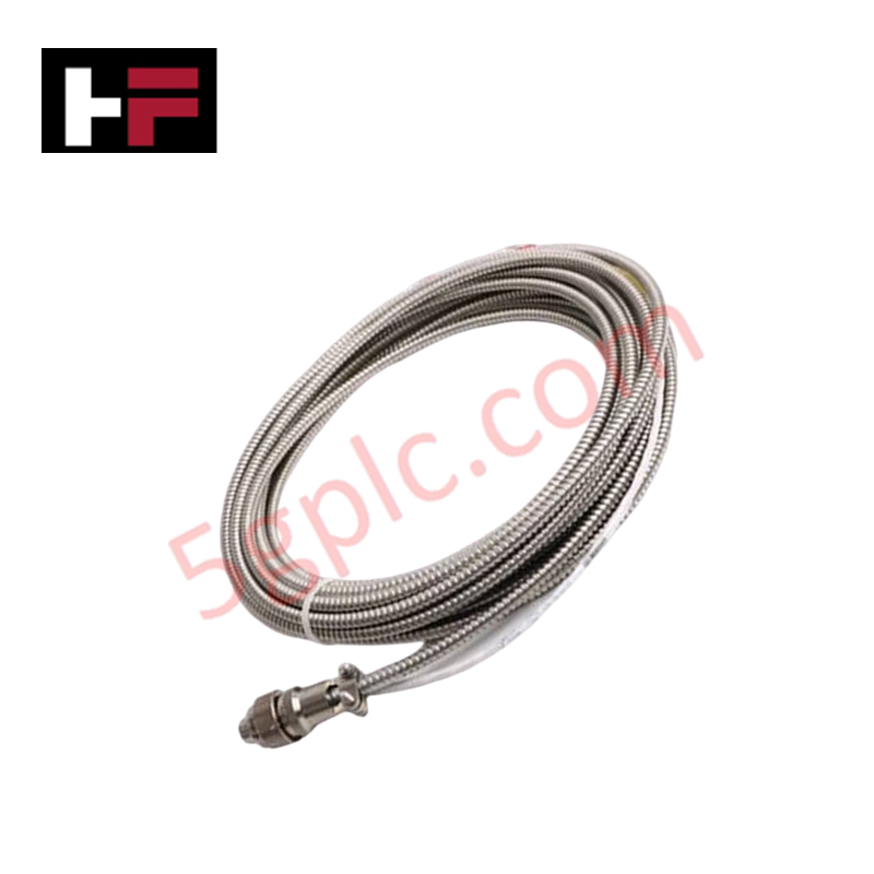
The Honeywell 51202329-102, also cataloged as the 51202329-102 I/O Link Cable Pair, operates as a dedicated hardware component for high-speed deterministic bus signal interconnections within Honeywell HC900 and I/O bus network architectures. It routes physical data traffic across 6 drops spaced at a 6-inch pitch, interfacing up to 2 redundant UIO IOTA (Input/Output Termination Assembly) bases across a 1.5-meter physical span.
Hardware Specifications
| Parameter | Specification |
|---|---|
| Model | 51202329-102 (Revision D) |
| Brand | Honeywell |
| Origin | USA |
| Weight | 0.1 kg |
| Dimensions | 1.5 m Length (6-inch Pitch between drops) |
| Operating Temp | -40 to 85 deg C |
| Power Consumption | Passive Cable Assembly (0 W) |
| Cable Type | I/O Link Cable Pair |
| Connection Drops | 6 drops for physical device attachment |
| Bus Compatibility | Up to 2 redundant UIO IOTAs |
Cold Junction Compensation & Signal Integrity
The 51202329-102 cable assembly provides low-attenuation physical coupling between processing nodes and termination assemblies. Shielding layers suppress high-frequency electrical noise across extended operational temperatures (-40 to 85 deg C), preventing noise induction onto adjacent low-level analog channels. This signal stability preserves measurement accuracy for thermocouple inputs utilizing onboard cold junction compensation (CJC) and transmitter loops running 4-20 mA HART loop protocol communications.
Frequently Asked Questions
Q: Can the 51202329-102 I/O link cable be connected or disconnected while the controller system is powered?
A: Cable disconnection must occur only when the corresponding I/O bus segment is powered down or isolated to avoid momentary communication loss and signal distortion on active channels.
Q: What physical spacing constraints apply to the drop connectors on this cable assembly?
A: The cable feature set includes 6 drop connection points fixed at a 6-inch pitch along the 1.5-meter cable span to fit standardized cabinet DIN-rail layouts.
Field Installation Guidelines
- Inspect cable insulation and connector pins for physical damage before routing inside the control enclosure.
- Route the cable pair away from high-voltage AC power lines and variable frequency drives to eliminate electromagnetic coupling.
- Observe standard minimum bend radius rules during installation to prevent internal conductor strain or shield separation.
- Ensure connector locking mechanisms are fully engaged on all active UIO IOTA interfaces to prevent loose mechanical contact.
Additional Information
- 100% Genuine Parts: All products are original and authentic, ensuring reliable industrial performance.
- 30-Day Refund Guarantee: Return any in-stock item within 30 days in original, unopened packaging for a full refund (excluding shipping and fees).
- 12-Month Warranty: Covers defects in materials or workmanship; excludes misuse, normal wear, or unauthorized modifications.
- Worldwide Shipping: We ship via USPS, UPS, FedEx, and DHL. Delivery times vary by country and may be subject to customs or import fees.
- Support & Contact: Technical and warranty assistance is available anytime. Contact us here: Contact.
- Purchase Guidance: Check product specifications and compatibility carefully before ordering to ensure proper application.




Tech & Buying Guide

Understanding PLC Digital Output Types: Relay, Transistor, and Triac Explained
Programmable Logic Controllers (PLCs) form the backbone of modern industrial automation systems. They interface directly with field devices such as solenoid valves, indicator lights, motor starters, and interposing relays. Selecting the correct digital output module ensures high system availability and long hardware service life.

Understanding VFD Mechanical Brake Logic and Control in Industrial Automation
Variable Frequency Drives (VFDs) play a crucial role in modern industrial automation by controlling motor speed, torque, and acceleration. However, high-inertia loads and vertical lifting systems require precise mechanical braking logic to ensure operational safety and prevent equipment damage.

Why Programmable Logic Controllers Drop into Stop Mode: An Expert Analysis
Industrial automation systems rely heavily on Programmable Logic Controllers (PLCs) to maintain uninterrupted production. When a PLC unexpectedly shifts from Run to Stop mode, whole manufacturing lines stall.
As control systems evolve across modern factory automation, understanding the root causes of these interruptions helps engineers minimize costly downtime. This technical guide breaks down why PLCs trip into Stop mode and provides practical strategies to mitigate system faults.