














Product Details
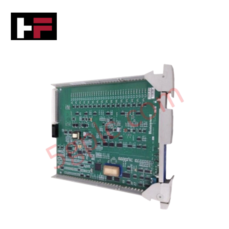
The Honeywell 51153818-104, also cataloged as the 51153818-104 Jumper Kit, operates as a dedicated hardware component for field termination assembly wiring and signal routing within Honeywell FTA Chassis platforms.
Hardware Specifications
| Parameter | Specification |
|---|---|
| Model | 51153818-104 |
| Brand | Honeywell |
| Origin | USA |
| Weight | 2 kg |
| Operating Temp | -40 to +85 deg C |
| Power Consumption | Passive passive hardware component |
| Function | Jumper termination hardware for FTA modules |
| Termination Type | Jumper termination hardware |
| Certifications | CE, UL approved |
| System Compatibility | Honeywell Field Termination Assemblies (FTA) |
4-20 mA HART Loop Protocol & Channel-to-Channel Isolation
The jumper kit maintains signal continuity and loop impedance integrity across Field Termination Assembly (FTA) backplane channels. Designed for zero-insertion-force stability, the jumpers establish reliable conductive bridging across adjacent terminal blocks without compromising channel-to-channel isolation parameters. The passive contact design supports unattenuated pass-through of analog measuring signals and high-frequency digital FSK telemetry associated with the 4-20 mA HART loop protocol.
Frequently Asked Questions
Q: What primary physical function does the 51153818-104 jumper kit fulfill on FTA modules?
A: It provides physical jumper termination bridges across terminal pins on Honeywell Field Termination Assemblies to complete specific wiring configurations.
Q: Does the 51153818-104 kit require separate electrical isolation barriers during installation?
A: No, the jumper hardware installs directly into designated FTA header positions while relying on the host assembly's channel-to-channel isolation architecture.
Field Installation Guidelines
- Disconnect or isolate field loop power prior to altering jumper configurations on the Field Termination Assembly (FTA).
- Align the jumper pins precisely with the terminal block headers to avoid bending conductive pins during insertion.
- Press the jumper down until the plastic housing seats flush against the FTA board barrier.
- Verify all field wiring shield drain wires are connected to the main cabinet ground bar to prevent noise pickup.
- Inspect all physical jumper links visually to ensure firm mechanical retention before re-energizing the loop.
Additional Information
- 100% Genuine Parts: All products are original and authentic, ensuring reliable industrial performance.
- 30-Day Refund Guarantee: Return any in-stock item within 30 days in original, unopened packaging for a full refund (excluding shipping and fees).
- 12-Month Warranty: Covers defects in materials or workmanship; excludes misuse, normal wear, or unauthorized modifications.
- Worldwide Shipping: We ship via USPS, UPS, FedEx, and DHL. Delivery times vary by country and may be subject to customs or import fees.
- Support & Contact: Technical and warranty assistance is available anytime. Contact us here: Contact.
- Purchase Guidance: Check product specifications and compatibility carefully before ordering to ensure proper application.


Tech & Buying Guide

Wellhead Control Panel (WHCP) Architecture in Oil and Gas Automation
Upstream oil and gas operations rely on specialized field control platforms to manage wellhead extraction safety and hydraulic actuation. A Wellhead Control Panel (WHCP) serves as a dedicated hydraulic and pneumatic power unit designed to operate critical Christmas Tree isolation valves. By interfacing field safety components directly with Programmable Logic Controller (PLC) architecture, a WHCP protects upstream extraction assets against overpressure, catastrophic leaks, and thermal emergencies.

Understanding Marshalling Cabinets in Industrial Control Systems Architecture
Industrial control system deployments rely on structured signal distribution to bridge field instrumentation with central processing hardware. A marshalling cabinet serves as the vital intermediate connection point between heavy field home-run multi-pair cables and delicate input/output (I/O) modules housed inside Programmable Logic Controller (PLC) or Distributed Control System (DCS) enclosures. By segregating field cable terminations from control hardware, engineers maintain system flexibility, safeguard controller components, and streamline commissioning workflows.

FAT vs SAT in Industrial Control Systems: Key Differences and Execution Guide
Industrial control system deployment relies on strict verification protocols to guarantee operational safety, system stability, and regulatory compliance. Commissioning complex Programmable Logic Controller (PLC) racks, Distributed Control Systems (DCS), and Safety Instrumented Systems (SIS) requires two critical milestones: the Factory Acceptance Test (FAT) and the Site Acceptance Test (SAT). Both procedures validate that system automation meets design specifications, but they occur at different stages of project execution and target distinct operational risks.