


Product Details
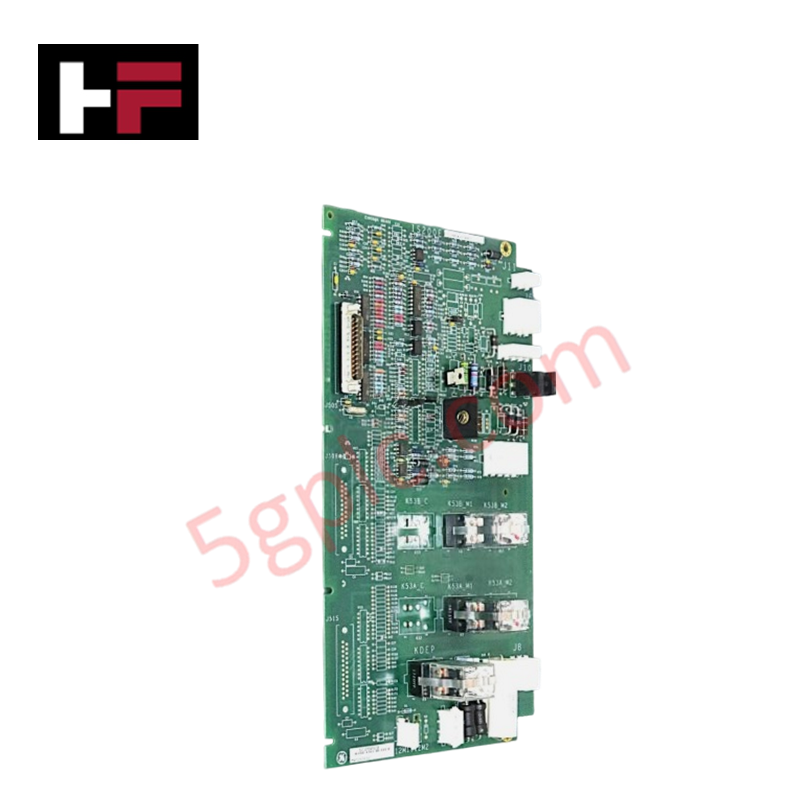
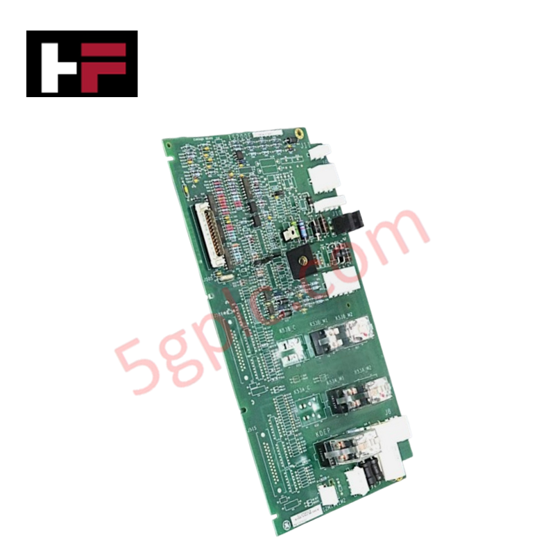
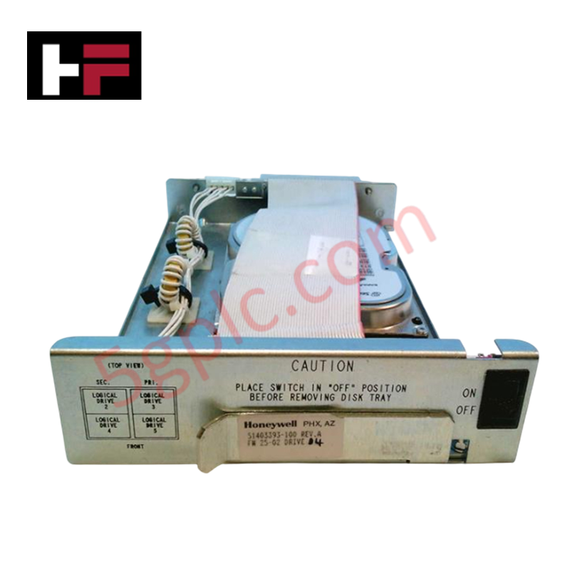
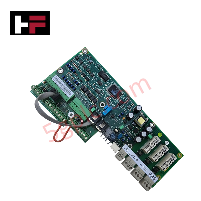
Configured for high-speed contactor and pilot relay management in EX2100 excitation systems, the General Electric IS200EXHSG4A (IS200EXHSG4A Exciter High-Speed Relay Driver Board) provides direct physical/electrical execution of field flashing, de-excitation, and contactor feedback monitoring.
Hardware Specifications
| Parameter | Specification |
|---|---|
| Model | IS200EXHSG4A |
| Brand | General Electric |
| Origin | United States (USA) |
| Control Type | Simplex |
| Contactor Type | 125 V dc coil |
| Bridge Rating | 500 A, 42 mm |
Industrial Control and Firmware Integration
The IS200EXHSG4A integrates with the EX2100 Exciter Backplane (EBKP) to support deterministic control of excitation peripherals. The board utilizes firmware-supported logic to condition status signals from the Exciter De-Excitation Board (EDEX) and the Crowbar control circuit, relaying these states to the Exciter Main Input/Output (EMIO) boards for centralized processing. Its architecture facilitates I/O density scaling by supporting both simplex and redundant control configurations. The module provides conditioned 70 V dc excitation for contact inputs 41, 53A, and 53B, ensuring accurate state feedback monitoring to the control network.
Frequently Asked Questions (FAQ)
Q: What is the primary communication pathway for the IS200EXHSG4A?
A: The board interfaces directly with the Exciter Backplane Board (EBKP), which routes status and control signals to either a single EMIO board in simplex mode or three EMIO boards in redundant control configurations.
Q: How are field flashing and de-excitation managed by this board?
A: The board provides dedicated driver circuits for pilot relays, including 53A and 53B for field flashing, and the KDEP relay for de-excitation sequences, ensuring high-speed operation during critical transition events.
Field Installation Guidelines
- Mechanical Mounting: Install the board within the excitation control cabinet, ensuring alignment with the EBKP backplane connectors. Secure all mounting screws to provide a consistent electrical ground path.
- Wiring and Termination: Utilize the designated input/output terminals for contactor coil connections (125 V dc). Ensure all field wiring is adequately sized to handle the current requirements of the contactors and pilot relays.
- Feedback Verification: Before energizing, verify the continuity of the contact inputs (41, 53A, 53B) to the EXHS board. Confirm that the 70 V dc wetting voltage is present at the input terminals when the excitation power supply is active.
- EMI Mitigation: Route control and feedback wiring separately from high-power excitation bus bars. Use shielded conductors for signal lines to prevent induced common-mode noise from affecting the state monitoring of the crowbar and de-excitation status signals.
Additional Information
- 100% Genuine Parts: All products are original and authentic, ensuring reliable industrial performance.
- 30-Day Refund Guarantee: Return any in-stock item within 30 days in original, unopened packaging for a full refund (excluding shipping and fees).
- 12-Month Warranty: Covers defects in materials or workmanship; excludes misuse, normal wear, or unauthorized modifications.
- Worldwide Shipping: We ship via USPS, UPS, FedEx, and DHL. Delivery times vary by country and may be subject to customs or import fees.
- Support & Contact: Technical and warranty assistance is available anytime. Contact us here: Contact.
- Purchase Guidance: Check product specifications and compatibility carefully before ordering to ensure proper application.

Tech & Buying Guide

Mastering the Factory Acceptance Test (FAT) for PLC Control Panels: An Expert Guide
The Factory Acceptance Test (FAT) is a vital milestone in industrial automation that ensures custom PLC panels meet exact design specifications before dispatch. This guide outlines the step-by-step FAT procedure and key industry best practices to prevent costly site delays and ensure long-term operational success.

Redundant Automation Systems: Ensuring Continuous Uptime in Critical Control Infrastructure
System reliability directly determines operational profitability across high stakes process industries. Modern industrial automation platforms must eliminate single points of failure to prevent catastrophic shutdowns. Deploying fault tolerant architecture safeguards complex facilities against unexpected hardware glitches, network disruptions, and maintenance outages.

Understanding Types of Noise in Electronic Circuits and Control Systems
Signal integrity directly determines measurement accuracy and loop stability across industrial automation environments. Electronic noise introduces unwanted stochastic interference into analog loops, sensor feedback lines, and digital fieldbus networks. Understanding how intrinsic electronic noise and external electromagnetic interference manifest allows control engineers to optimize signal conditioning and shield sensitive instrumentation effectively.