














Product Details
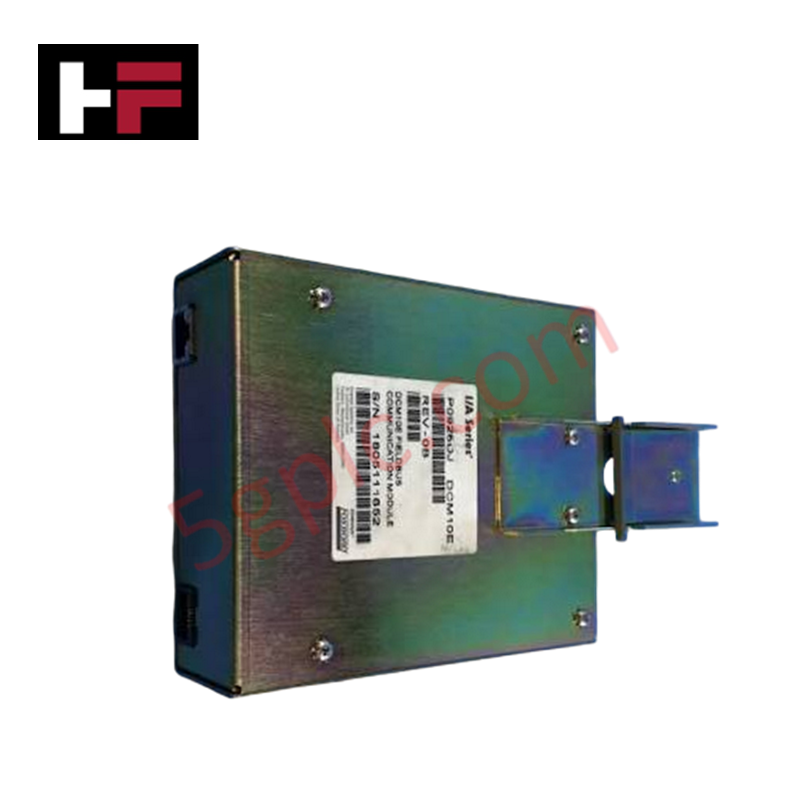
The Foxboro DCM10E P0926DJ, also cataloged as the DCM10E P0926DJ Fieldbus Communication Modules, operates as a dedicated hardware component for protocol level signal transformation within Foxboro I/A Series distributed control systems. The module converts 10 Mbps Ethernet signals into 268.75 kbps HDLC signals to enable bi-directional data flow between the Control Processor 60 (CP60) and downstream Y-Module form factor Fieldbus Modules (FBMs) or migration modules.
Hardware Specifications
| Parameter | Specification |
|---|---|
| Model | DCM10E P0926DJ |
| Brand | Foxboro |
| Origin | USA |
| Operating Temp | Standard industrial enclosure range |
| Power Consumption | 6.5 W (maximum) |
| Input Power Option 1 | 26 VDC to 42 VDC (nominal), 250 mA max, supplied from Power Distribution Unit (P0904AU) |
| Input Power Option 2 | 15 VDC to 19.5 VDC (nominal), 30 mA + load current (200 mA max via IPM 6 Unit) |
| Input Power Option 3 | External 24 VDC +/- 15%, 300 mA max |
| Signal Conversion | 10 Mbps Ethernet signals to 268.75 kbps HDLC signals |
| Redundancy | Pair-configurable dual module architecture |
| Status Diagnostics | Integrated LED indicators for transmit, receive, and fail status |
| Compatibility | Control Processor 60 (CP60), Y-Module FBMs, migration modules |
| Product Type | Fieldbus Communication Modules |
4-20 mA HART Loop Protocol and Channel Isolation
The DCM10E P0926DJ incorporates internal channel-to-channel isolation architecture to prevent common-mode noise and ground loops from compromising backplane communications. When routing process parameters from field devices operating on 4-20 mA HART loop protocol transmitters or FOUNDATION Fieldbus segments through connected FBM subsystems, the converter preserves packet integrity during conversion. Thermally balanced component layouts minimize internal heat generation, protecting signal reference nodes and maintaining conversion timing stability across variable ambient cabinet temperatures.
Frequently Asked Questions
Q: How does the DCM10E handle module redundancy in critical control loops?
A: Modules can be installed in paired configurations; if the primary unit experiences a hardware fault, communication automatically fails over to the redundant partner without disrupting backplane data traffic.
Q: What power options are supported for main and backup operation?
A: The module accepts 26 to 42 VDC from a P0904AU Power Distribution Unit, 15 to 19.5 VDC via IPM 6 for battery backup operation, or a standard external 24 VDC supply (+/- 15%).
Q: What visual diagnostics are available on the module faceplate?
A: The front panel includes dedicated LED indicators for transmit activity, receive activity, and module fail status to facilitate immediate physical troubleshooting.
Field Installation Guidelines
- Mount the DCM10E module vertically onto the standard DIN rail mounting slot inside the field enclosure.
- Confirm the system power distribution unit is de-energized or verified safe prior to connecting power input wiring.
- Wire the selected power source (P0904AU PDU, IPM 6 battery backup unit, or external 24 VDC line) to the terminal block, observing correct voltage parameters.
- Attach the 10 Mbps Ethernet cable from the CP60 host and the HDLC fieldbus cabling to the Y-Module FBM network interface ports.
- Terminate all fieldbus cable shielding at the single-point cabinet instrument ground bar to suppress electromagnetic interference.
- Apply power and verify that the transmit/receive LEDs indicate active communication and the fail LED remains unlit.
Additional Information
- 100% Genuine Parts: All products are original and authentic, ensuring reliable industrial performance.
- 30-Day Refund Guarantee: Return any in-stock item within 30 days in original, unopened packaging for a full refund (excluding shipping and fees).
- 12-Month Warranty: Covers defects in materials or workmanship; excludes misuse, normal wear, or unauthorized modifications.
- Worldwide Shipping: We ship via USPS, UPS, FedEx, and DHL. Delivery times vary by country and may be subject to customs or import fees.
- Support & Contact: Technical and warranty assistance is available anytime. Contact us here: Contact.
- Purchase Guidance: Check product specifications and compatibility carefully before ordering to ensure proper application.


Tech & Buying Guide

Demystifying the DDE Protocol in Legacy Industrial Automation Systems
Modern control systems rely heavily on seamless interprocess communication to exchange operational data between software programs. Microsoft first introduced the Dynamic Data Exchange (DDE) protocol in 1987 to enable real-time data sharing. In factory automation, DDE served as an early bridge between control software and Windows desktop applications. Therefore, understanding DDE mechanics provides crucial insights into how legacy industrial networks established software-level connectivity.

Demystifying CPU Communication Ports in Siemens PLC Architectures
Industrial automation relies heavily on robust data exchange between devices. Without seamless connectivity, field instruments, network switches, human-machine interfaces, and programmable logic controllers cannot coordinate effectively. Therefore, understanding the various CPU communication ports available in Siemens hardware ensures efficient factory automation design and seamless system integration.

Mastering the Siemens PLC Scan Cycle: How the CPU Executes Automation Programs
Industrial automation relies heavily on programmable logic controllers (PLCs) to manage complex manufacturing processes. Many engineers dive straight into programming without mastering the underlying architecture. However, understanding how a PLC CPU executes a program ensures reliable system design. Therefore, mastering the scan cycle optimizes both performance and troubleshooting in modern control systems.