










Product Details
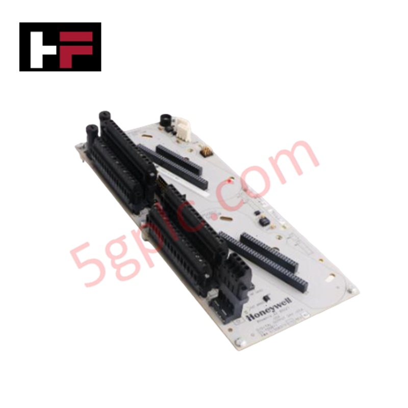
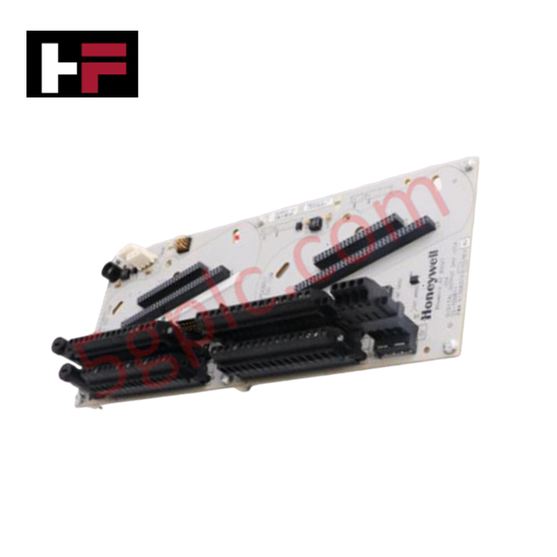
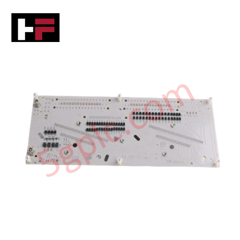
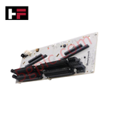
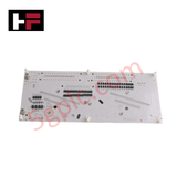
The Honeywell DC-TFB412 51307618-176 serves as the primary DC-TFB412 Control Module Backplane utilized to execute physical module integration and signal routing across Honeywell C300 controller platforms. The hardware chassis operates as the centralized electrical distribution plane, providing structured interconnect rails that bridge internal controller processing logic with external input/output hardware topologies.
Hardware Specifications
| Parameter | Specification |
|---|---|
| Model | DC-TFB412 51307618-176 |
| Brand | Honeywell |
| Series / Module Type | Experion C300 / Control Module Backplane |
| Origin | USA |
| Weight | 0.5 kg |
| Dimensions | 10 cm x 18 cm x 10 cm |
| Operating Temp | -40 to +70 deg C |
| Power Supply | 24 VDC nominal |
| Compatibility | Honeywell C300 Controllers |
| Interface Capability | Dedicated high-speed internal module bus routing |
| Mounting Structure | Integrated carrier rail mounting profile |
Channel-to-Channel Isolation and Controller Interface Dynamics
The DC-TFB412 51307618-176 hardware fabric is designed with dedicated trace shielding to establish strict channel-to-channel isolation between adjacent expansion cards. Operating on a continuous 24 VDC power bus distribution structure, the multi-layer printed circuit board layout suppresses electromagnetic cross-talk and limits inductive loop interference across high-frequency pathways. This architecture guarantees the signal propagation velocity required for high-density analog and digital data streams, ensuring uncorrupted transmission of 4-20 mA HART loop protocol parameters between the field termination nodes and the core C300 controller.
Frequently Asked Questions
Q: How does the backplane protect the C300 controller if an individual I/O module suffers an internal short circuit?
A: The backplane incorporates integrated circuit path isolation and distinct power trace shielding for each physical slot. This topology restricts localized overcurrent faults to the specific faulted module interface channel, preventing voltage drops across the shared 24 VDC bus from disrupting the primary C300 processor operations.
Q: Is online hot-swap of I/O modules supported on this backplane configuration?
A: The physical backplane traces and connector arrays are designed to withstand transient insertion currents during live-insertion sequences. However, hot-swap procedures must strictly align with the safety interlock and grounding rules defined for the specific I/O module type being serviced.
Field Installation Guidelines
- Mechanical Mounting Execution: Secure the backplane frame onto the horizontal mounting rail system within the enclosure. Verify all integrated grounding lugs achieve direct metal-to-metal continuity with the structural cabinet frame.
- 24 VDC Power Wiring: Direct the primary 24 VDC supply lines into the designated power input block. Ensure the conductor cores are fully stripped and clamped to prevent loose terminations from introducing micro-interruptions into the control bus.
- Module Insertion Alignment: Align the I/O modules vertically with the guide slots before applying insertion force. Check that the connector pins engage smoothly without bending to preserve the integrity of the channel-to-channel isolation parameters.
- Thermal Monitoring: Ensure the spatial boundaries around the backplane match or exceed the minimum clearance specifications. This maintains unobstructed passive convection pathways needed to keep the hardware within the -40 to +70 deg C temperature operational envelope.
Additional Information
- 100% Genuine Parts: All products are original and authentic, ensuring reliable industrial performance.
- 30-Day Refund Guarantee: Return any in-stock item within 30 days in original, unopened packaging for a full refund (excluding shipping and fees).
- 12-Month Warranty: Covers defects in materials or workmanship; excludes misuse, normal wear, or unauthorized modifications.
- Worldwide Shipping: We ship via USPS, UPS, FedEx, and DHL. Delivery times vary by country and may be subject to customs or import fees.
- Support & Contact: Technical and warranty assistance is available anytime. Contact us here: Contact.
- Purchase Guidance: Check product specifications and compatibility carefully before ordering to ensure proper application.


Tech & Buying Guide

Demystifying CPU Communication Ports in Siemens PLC Architectures
Industrial automation relies heavily on robust data exchange between devices. Without seamless connectivity, field instruments, network switches, human-machine interfaces, and programmable logic controllers cannot coordinate effectively. Therefore, understanding the various CPU communication ports available in Siemens hardware ensures efficient factory automation design and seamless system integration.

Mastering the Siemens PLC Scan Cycle: How the CPU Executes Automation Programs
Industrial automation relies heavily on programmable logic controllers (PLCs) to manage complex manufacturing processes. Many engineers dive straight into programming without mastering the underlying architecture. However, understanding how a PLC CPU executes a program ensures reliable system design. Therefore, mastering the scan cycle optimizes both performance and troubleshooting in modern control systems.

How to Connect to Siemens S7 PLCs: 5 Essential Communication Methods
Establishing a reliable hardware link between a programming terminal and a Siemens SIMATIC controller is essential for engineering workflows. Field engineers rely on distinct physical layers, ranging from legacy serial connections to high-speed Industrial Ethernet protocols. Modern factory automation environments prioritize fast data transfer and seamless driver integration. Selecting the correct connection method simplifies program downloads, online monitoring, and system troubleshooting in complex control systems.