












Product Details
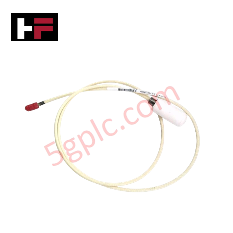
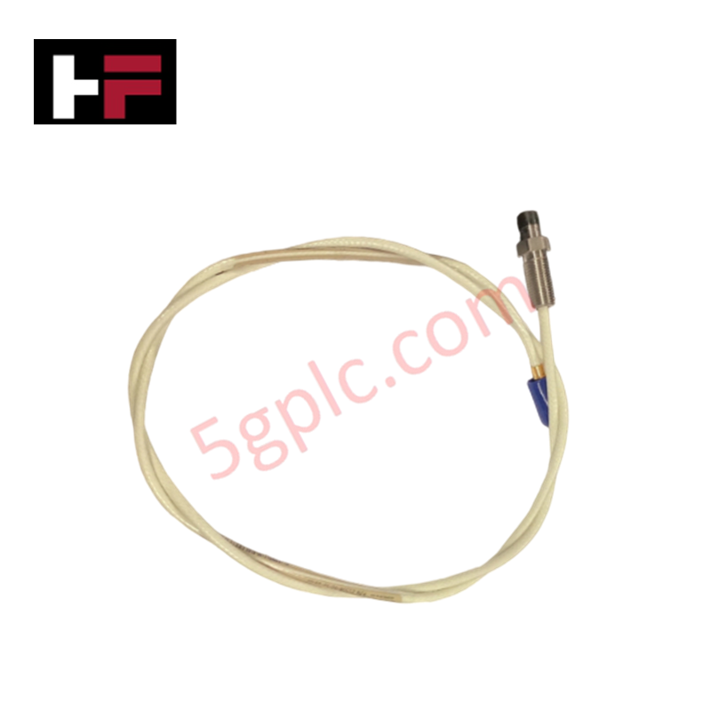
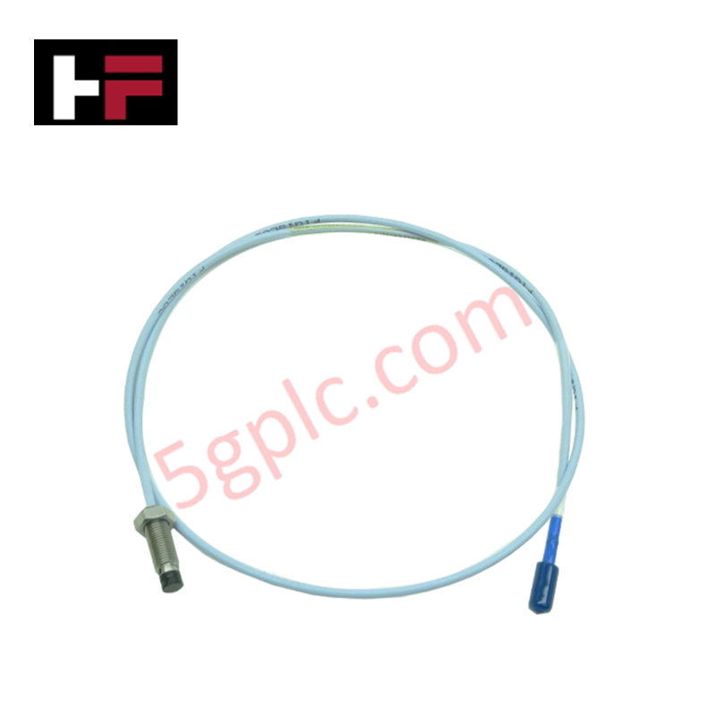
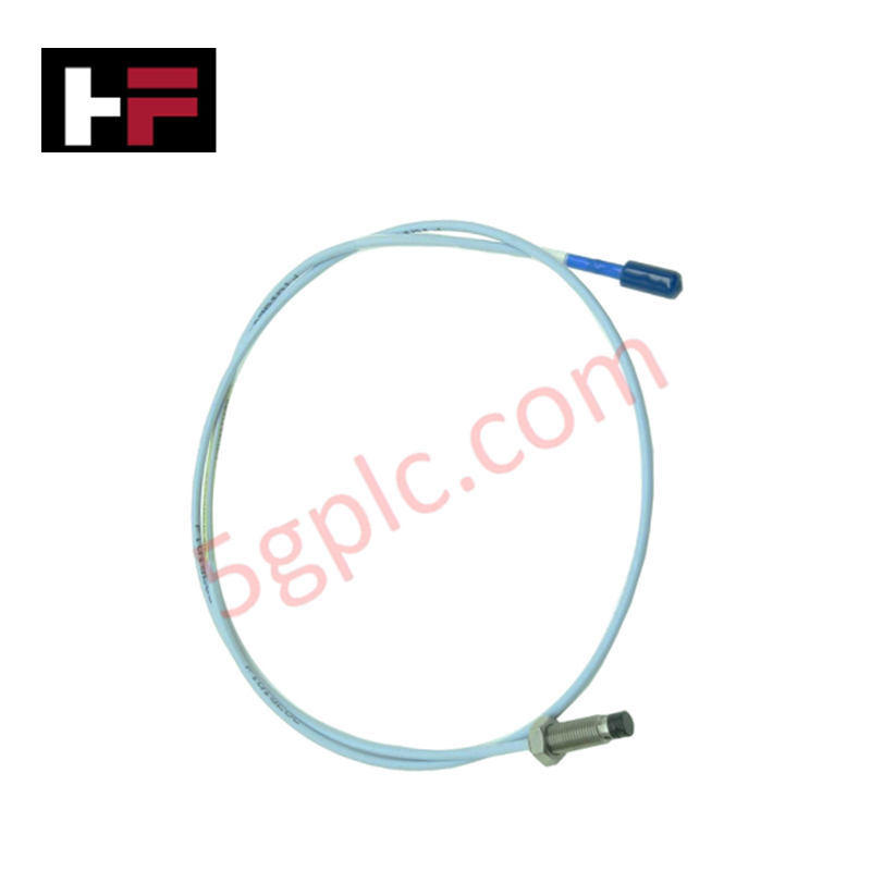
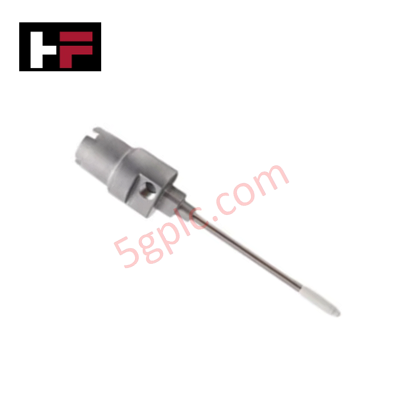
The Bently Nevada 21508-02-12-10-02, also cataloged as the 21508 Proximity Sensors, operates as a dedicated hardware component for non-contact dynamic vibration and axial position measurement within machinery protection systems.
Suffix Breakdown & Model Matrix
| Option Field | Code | Configuration Detail |
|---|---|---|
| Thread Option | 02 | 3/8-24 UNF thread format |
| Unthreaded Length | 12 | 1.2 in unthreaded length |
| Overall Case Length | 10 | 1.0 in case length |
| Total Cable Length | 02 | 1.0 m (39 in) integral cable length |
Hardware Specifications
| Parameter | Specification |
|---|---|
| Model | 21508-02-12-10-02 |
| Brand | Bently Nevada |
| Origin | USA |
| Weight | 0.04 kg (0.09 lbs) |
| Dimensions | 8 mm probe tip diameter, 3/8-24 UNF reverse mount body |
| Operating Temp | -51 deg C to +177 deg C (-60 deg F to +351 deg F) |
| Power Consumption | Passive transducer powered via Proximitor Sensor loop |
| Mounting Type | Reverse mount 8 mm proximity probe |
| Cable Type | 1.0 m (39 in) integral cable with miniature male coaxial connector |
| Probe Scaling | Standard 7.87 V/mm (200 mV/mil) with matching Proximitor Sensor |
Eddy-Current Probe Scaling and Gap Voltage Validation
The 21508-02-12-10-02 reverse-mount probe utilizes high-frequency eddy-current probe scaling to convert target gap distances into linear electrical voltages. When driven by a matched Proximitor Sensor, the output yields a nominal scale factor of 7.87 V/mm (200 mV/mil) for ferromagnetic targets such as AISI 4140 steel. Setting the mechanical installation bias to achieve -10 VDC gap voltage validation establishes the sensor at the midpoint of its calibrated linear range, providing symmetric headroom for high-amplitude dynamic vibration analysis and precise rotor dynamics tracking.
Frequently Asked Questions
Q: How is the miniature male coaxial connector insulated from machine electrical ground?
A: The connector terminal must be fitted with a high-dielectric silicone insulator boot to prevent grounding of the coaxial outer conductor at the machine casing.
Q: What is the primary functional difference of the reverse-mount housing configuration?
A: The reverse-mount body is threaded from the rear, allowing the transducer to be installed through internal bearing housings or mounting brackets where front-access clearance is limited.
Field Installation Guidelines
- Thread the reverse-mount probe body into the tapped mounting bracket or sleeve inside the bearing housing.
- Advance the sensor tip toward the target shaft surface while measuring DC voltage across the Proximitor Sensor output terminals.
- Lock the mounting jam nut once the multimeter indicates the target gap voltage of -10 VDC.
- Route the integral 1.0 m cable away from sharp edges, hot surfaces, and high-voltage power leads.
- Connect the miniature male coaxial connector to the Proximitor extension cable and slide a protective insulating sleeve over the connector junction.
Additional Information
- 100% Genuine Parts: All products are original and authentic, ensuring reliable industrial performance.
- 30-Day Refund Guarantee: Return any in-stock item within 30 days in original, unopened packaging for a full refund (excluding shipping and fees).
- 12-Month Warranty: Covers defects in materials or workmanship; excludes misuse, normal wear, or unauthorized modifications.
- Worldwide Shipping: We ship via USPS, UPS, FedEx, and DHL. Delivery times vary by country and may be subject to customs or import fees.
- Support & Contact: Technical and warranty assistance is available anytime. Contact us here: Contact.
- Purchase Guidance: Check product specifications and compatibility carefully before ordering to ensure proper application.

Tech & Buying Guide
Mastering Modern Industrial Joystick Controls in Heavy Automation
Industrial joysticks play a pivotal role in human-machine interaction across heavy material handling and mobile hydraulics. These tactile controllers translate complex operator movements into precise electrical signals for PLCs, motion controllers, and DCS networks. Consequently, selecting and installing the right joystick architecture ensures operator safety, reduces fatigue, and optimizes equipment performance.

Navigating Industrial Automation Failures: Types, Causes, and Mitigation Strategies
Modern manufacturing relies heavily on automated control systems to maximize throughput and maintain product quality. However, unplanned downtime in industrial automation can cost facility operators thousands of dollars per hour. Understanding how programmable logic controllers (PLCs), distributed control systems (DCS), and field instrumentation fail empowers engineering teams to implement robust preventive maintenance strategies.

Essential Motion Control Commands: A Practical Guide for Engineers
Automation engineers often rely on precise position and speed control to drive modern factory machinery. Modern industrial systems, such as Programmable Logic Controllers (PLCs) and Distributed Control Systems (DCS), depend heavily on standardized motion instructions. Mastering these commands ensures operational safety, protects mechanical components, and optimizes cycle times across production lines.