










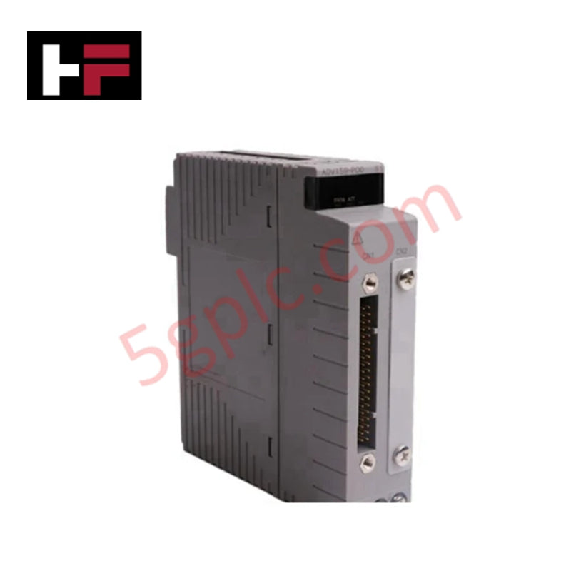
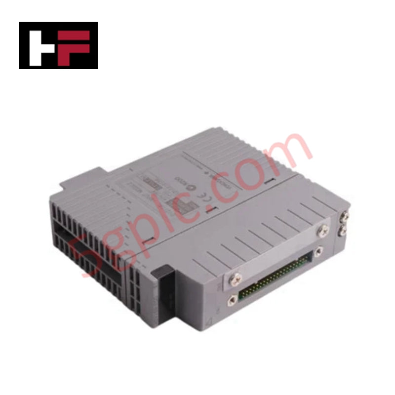
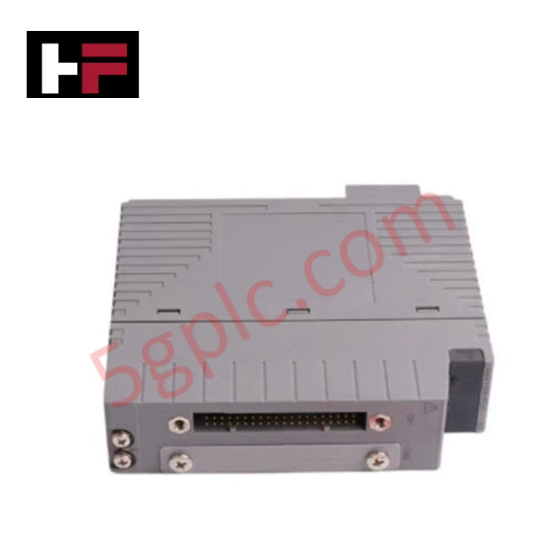
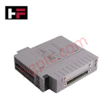
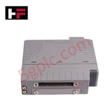
Product Details
Part Number Breakdown: ADV159-P01
Yokogawa utilizes specific alphanumeric codes to denote functionality and hardware revisions:
-
ADV159: Digital Input Module (32-channel, Isolated).
-
-P: Pressure-clamp terminal connection style.
-
0: Standard type hardware specification.
-
1: Updated model version for enhanced signal stability and subrack compatibility.
Technical Specifications
The ADV159-P01 provides precise electrical thresholds for reliable binary signal detection.
-
Number of Channels: 32, fully isolated
-
Contact Input Requirements: * ON Signal: 200 $\Omega$ or less
-
OFF Signal: 100 k$\Omega$ or more
-
Short Circuit Current: 1.25 mA (Minimum)
-
Voltage Input Thresholds: * ON Signal: $\pm$1 V DC
-
OFF Signal: 4.5 to 25 V DC
-
Input Contact Rating: 5 V DC, 20 mA or more
-
Response Time: * Status Input: $\le$ 8 ms
-
Pushbutton Input: $\le$ 20 ms
-
Output Signal: Transistor contact (for status feedback)
-
Output Rating: 30 V DC, 100 mA (Inductive/Resistive loads)
Engineering Advantages
-
Native Pushbutton Logic: The ADV159-P01 includes dedicated firmware support for pushbutton inputs. This feature eliminates the need for complex software debouncing or latching logic in the main controller, reducing CPU overhead and simplifying operator interface programming.
-
High-Integrity Channel Isolation: Individual channel isolation prevents electrical noise, ground loops, and cross-channel interference. This architecture ensures that a fault on one field instrument does not propagate to neighboring channels or the internal DCS system bus.
-
Dual-Signal Versatility: The module accommodates both dry contact and voltage-level signals. This versatility allows engineers to mix different types of field instrumentation on a single module, optimizing rack space and reducing the total variety of spare parts required.
-
Rapid Response Execution: An 8 ms response time for status inputs enables real-time tracking of high-speed industrial sequences. This speed proves vital for sequence-of-events (SOE) recording and safety-critical interlocking where millisecond accuracy prevents equipment downtime.
-
Rugged Transistor Outputs: Integrated transistor contacts drive small relays or signaling LEDs directly. Supporting up to 100 mA at 30 V DC, these outputs provide local feedback loops without requiring additional digital output cards.
FAQs
-
Does the ADV159-P01 require an external power supply for inputs?
The module provides the necessary sensing voltage for dry contact inputs. However, if you utilize the voltage input mode, the field device must provide the 4.5 to 25 V DC signal level to trigger the OFF state.
-
What is the primary application for the 20 ms pushbutton response time?
The 20 ms window acts as a built-in filter to distinguish intentional operator actions from mechanical contact bounce or transient electrical interference, ensuring the DCS registers a clean, singular command.
-
Can I mix inductive and resistive loads on the transistor outputs?
Yes. The output contacts handle both load types up to 100 mA. For highly inductive loads, we recommend installing external suppression diodes to protect the transistor junctions from back-EMF spikes.
-
How does the P01 version differ from the P00 version?
The P01 is a hardware revision that often includes updated internal components for better thermal performance or component longevity. It maintains full backward compatibility with P00 configurations in your CENTUM VP software.
Additional Information
- 100% Genuine Parts: All products are original and authentic, ensuring reliable industrial performance.
- 30-Day Refund Guarantee: Return any in-stock item within 30 days in original, unopened packaging for a full refund (excluding shipping and fees).
- 12-Month Warranty: Covers defects in materials or workmanship; excludes misuse, normal wear, or unauthorized modifications.
- Worldwide Shipping: We ship via USPS, UPS, FedEx, and DHL. Delivery times vary by country and may be subject to customs or import fees.
- Support & Contact: Technical and warranty assistance is available anytime. Contact us here: Contact.
- Purchase Guidance: Check product specifications and compatibility carefully before ordering to ensure proper application.




Tech & Buying Guide

Understanding VFD Mechanical Brake Logic and Control in Industrial Automation
Variable Frequency Drives (VFDs) play a crucial role in modern industrial automation by controlling motor speed, torque, and acceleration. However, high-inertia loads and vertical lifting systems require precise mechanical braking logic to ensure operational safety and prevent equipment damage.

Why Programmable Logic Controllers Drop into Stop Mode: An Expert Analysis
Industrial automation systems rely heavily on Programmable Logic Controllers (PLCs) to maintain uninterrupted production. When a PLC unexpectedly shifts from Run to Stop mode, whole manufacturing lines stall.
As control systems evolve across modern factory automation, understanding the root causes of these interruptions helps engineers minimize costly downtime. This technical guide breaks down why PLCs trip into Stop mode and provides practical strategies to mitigate system faults.

Understanding Root Causes of Unplanned PLC Stop Mode in Industrial Automation
Modern Programmable Logic Controllers manage execution through distinct operational states: Run, Stop, Start-Up, and Hold. During power-up, a controller initializes memory registers within Stop mode before briefly transitioning to Start-Up mode. During this phase, internal self-diagnostics evaluate system integrity across hardware and user programs. If the controller detects no critical faults, it enters Run mode to execute the control program continuously. However, any severe system anomaly forces the CPU back into Stop mode immediately to prevent erratic machine behavior across the plant floor.