


Product Details
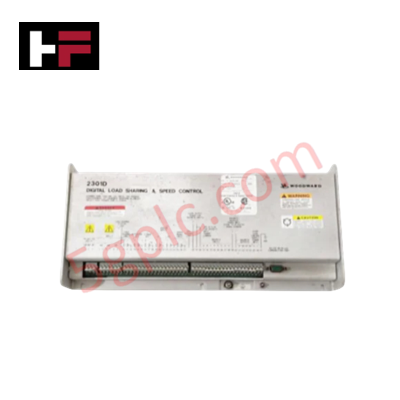
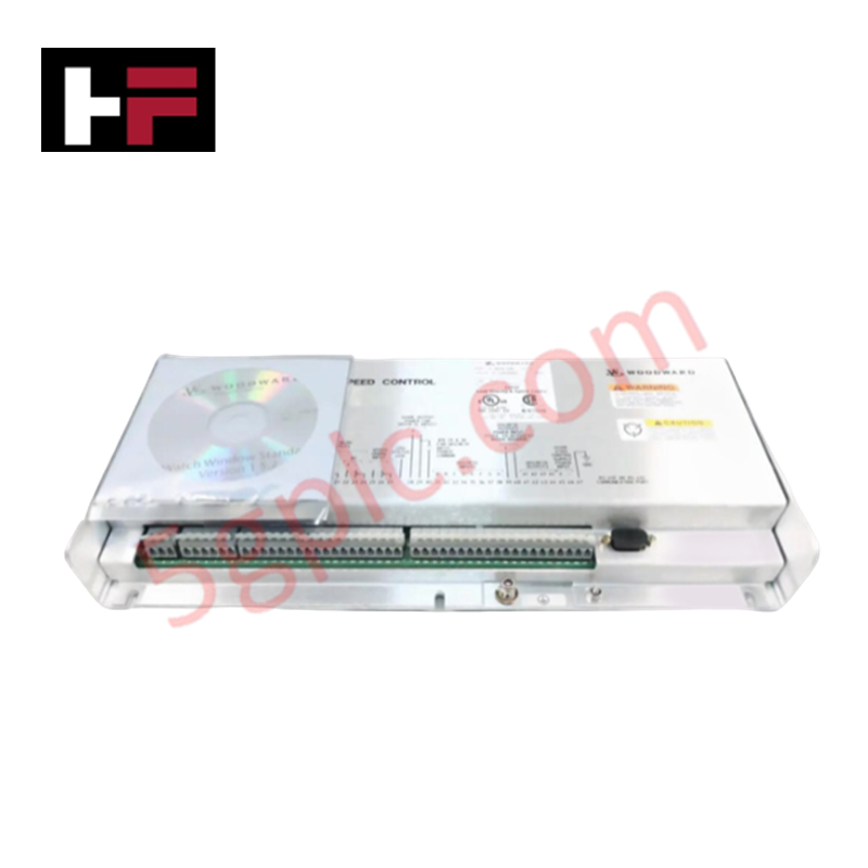
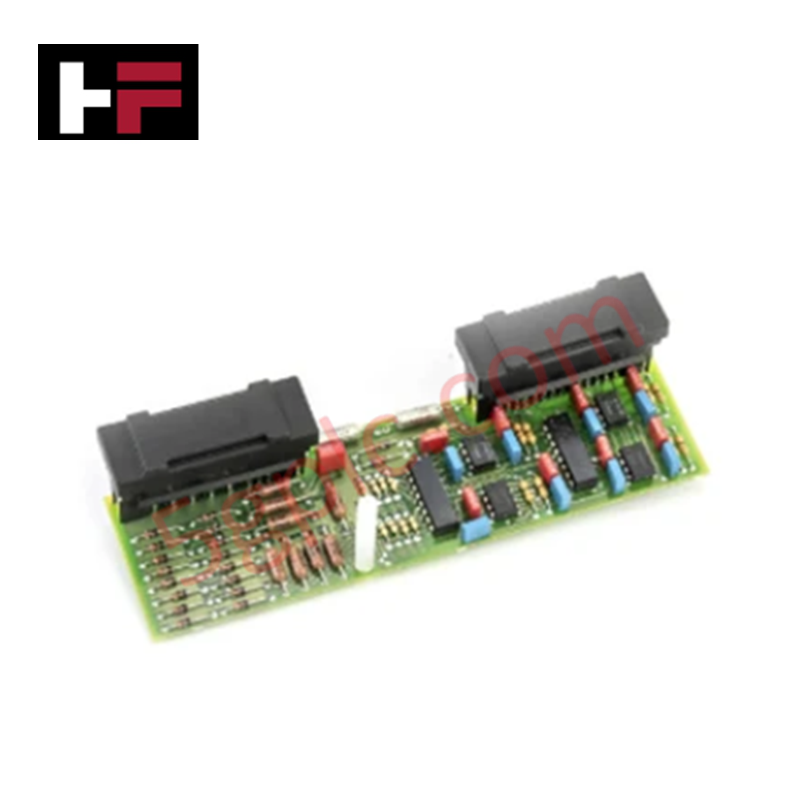
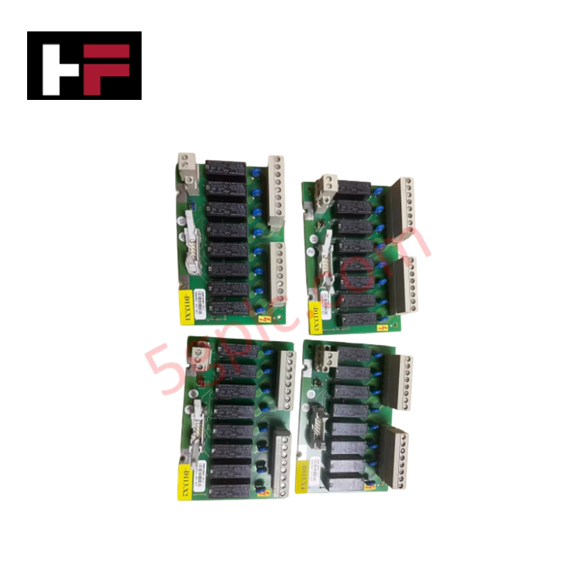
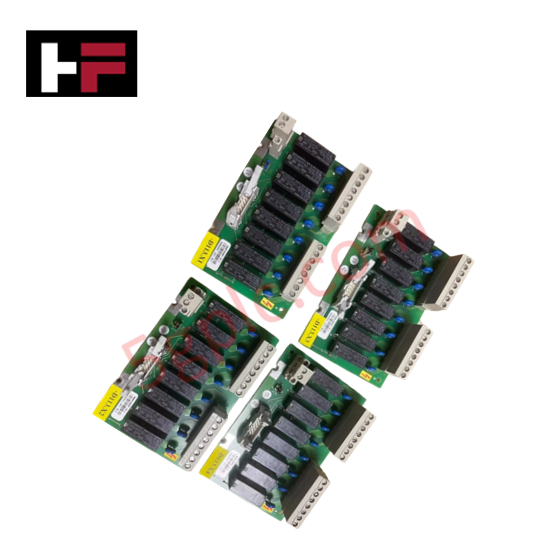
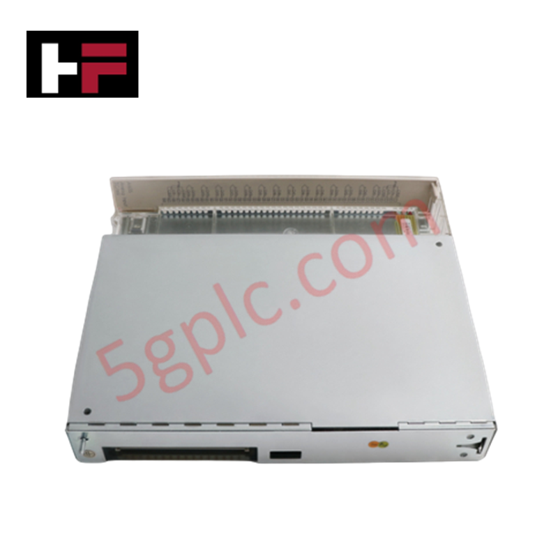
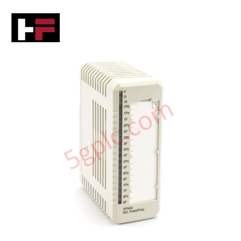
Configured for engine load management and frequency regulation, the Woodward 8273-140 (8273-140 Digital Load Sharing and Speed Control Module) provides direct physical/electrical execution of governing signals for industrial power generation.
Hardware Specifications
| Parameter | Specification |
|---|---|
| Model | 8273-140 |
| Brand | Woodward |
| Origin | Not specified |
| Weight | 1.0 kg |
| Power Consumption | 140 W |
| Input Voltage | 220 VAC |
| Output Voltage | 24 VDC |
| Frequency | 50/60 Hz |
Actuator Loop Feedback Response
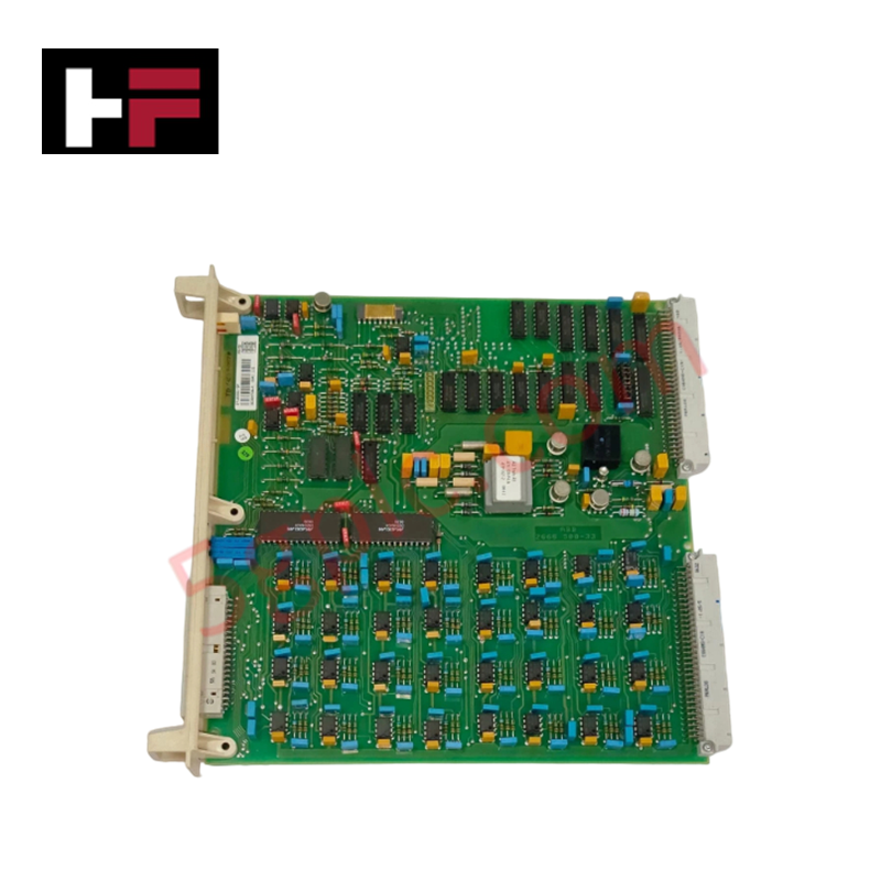
The 8273-140 employs a microprocessor-based control architecture to modulate fuel actuator position, ensuring synchronization and speed stability across varying load conditions. The module utilizes an integrated PID control loop to evaluate real-time frequency data, adjusting the 24 VDC output to compensate for transient engine disturbances. To prevent control instability, the actuator loop feedback response must be tuned according to the specific inertia and fuel system characteristics of the prime mover. Proper synchronization with secondary load-sharing units requires precise phase-angle matching and frequency drift monitoring, which can be validated via the PC-based diagnostic interface.
Frequently Asked Questions
Q: Does the microprocessor-based control support live PC-based diagnostic monitoring?
A: Yes, the module provides a data interface allowing users to connect a PC to perform testing, parameter adjustments, and analysis of logged fault data. Ensure the correct communication driver is installed to interface with the module's serial or Ethernet port.
Q: Are there specific grounding requirements for the 220 VAC input?
A: The AC input should be connected to a clean, transient-protected power source. The module chassis must be connected to the cabinet ground bus to provide a reference point for internal shielding and to prevent electromagnetic noise from impacting the sensitive microprocessor circuitry.
Field Installation Guidelines
- Mounting: Secure the module within a dry, vibration-dampened cabinet enclosure. Maintain clearance on all sides to allow for convection cooling of the internal power components.
- AC Input Wiring: Route 220 VAC input cabling away from low-voltage signal lines (MPU sensors, actuator feedback) to minimize inductive interference.
- Signal Grounding: Terminate all I/O shields at the designated ground stud on the control backplane. Ensure the signal ground is separate from the high-current power ground to avoid ground loop noise.
- Configuration: Utilize the PC-based software to establish the load-sharing droop and PID gains prior to initiating a live-load synchronization test.
- Validation: Monitor the output voltage stability at 24 VDC during engine cranking and transition to idle to confirm the governor is responding within the expected parameters.
Additional Information
- 100% Genuine Parts: All products are original and authentic, ensuring reliable industrial performance.
- 30-Day Refund Guarantee: Return any in-stock item within 30 days in original, unopened packaging for a full refund (excluding shipping and fees).
- 12-Month Warranty: Covers defects in materials or workmanship; excludes misuse, normal wear, or unauthorized modifications.
- Worldwide Shipping: We ship via USPS, UPS, FedEx, and DHL. Delivery times vary by country and may be subject to customs or import fees.
- Support & Contact: Technical and warranty assistance is available anytime. Contact us here: Contact.
- Purchase Guidance: Check product specifications and compatibility carefully before ordering to ensure proper application.
Tech & Buying Guide

Understanding Dry Contacts in PLC Wiring: An Industrial Automation Guide
Mastering contact switching principles is essential for reliable control panels. Field devices and PLCs interface through dry or wet contacts. This technical guide examines the mechanics of dry contacts, explores their wiring architectures, and evaluates their key advantages in industrial automation.

Ultimate Commissioning Checklist for Industrial Automation Systems: An Engineering Guide
Commissioning is the most decisive phase of an industrial automation project, transforming control hardware and software into an operational facility. Thorough testing prevents costly startup delays and builds customer confidence. This guide covers essential checklists, electrical standards, and best practices.

Redundant Automation Systems: Core Architecture, Business Value, and Technical Advantages
Unplanned downtime poses a major financial threat to process manufacturing. To prevent costly interruptions, engineers deploy redundant PLC and DCS architectures that ensure continuous operation when hardware fails. This technical guide explores redundancy principles, critical system nodes, and real-world scenarios.