

Product Details
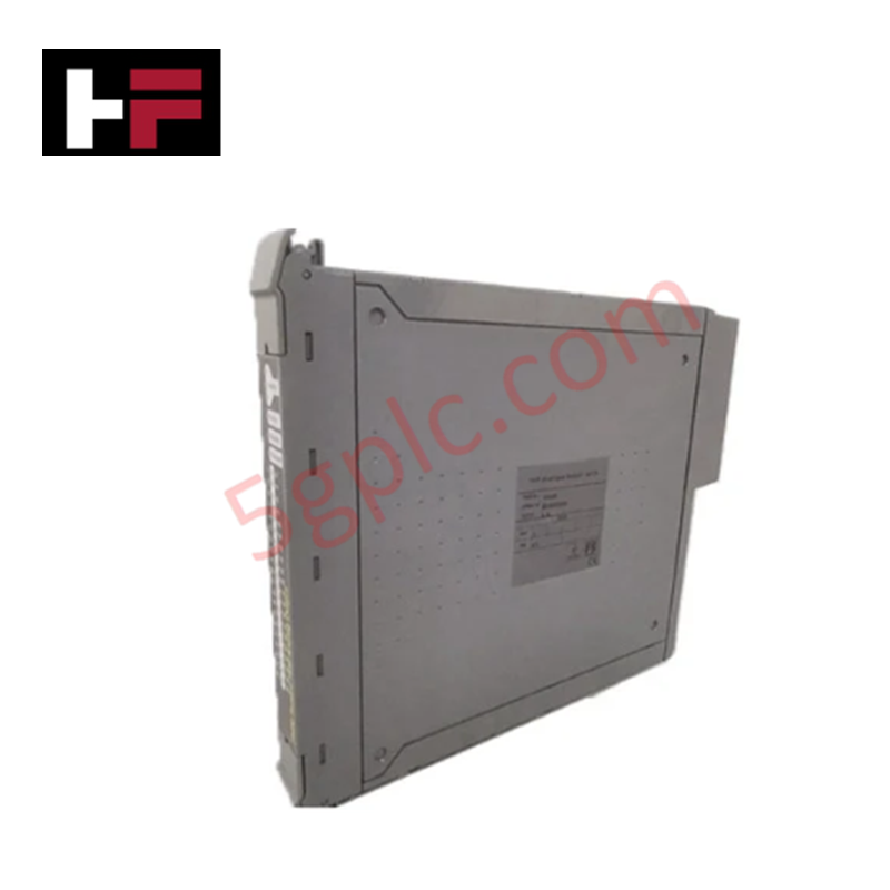
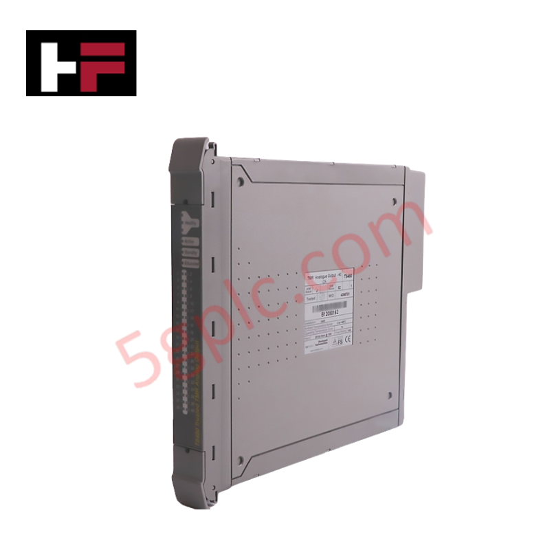
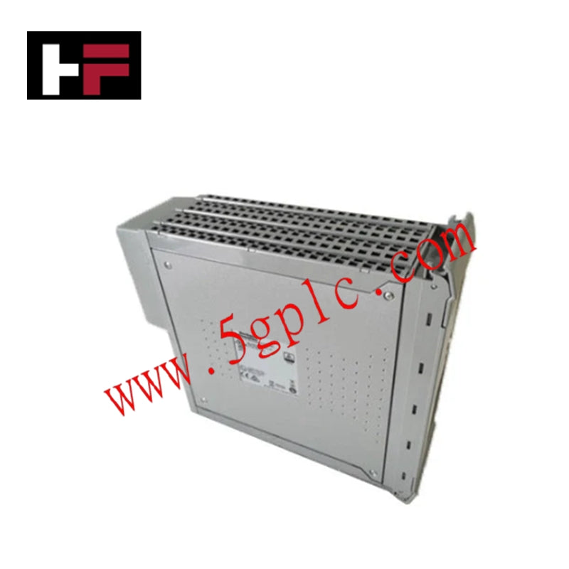
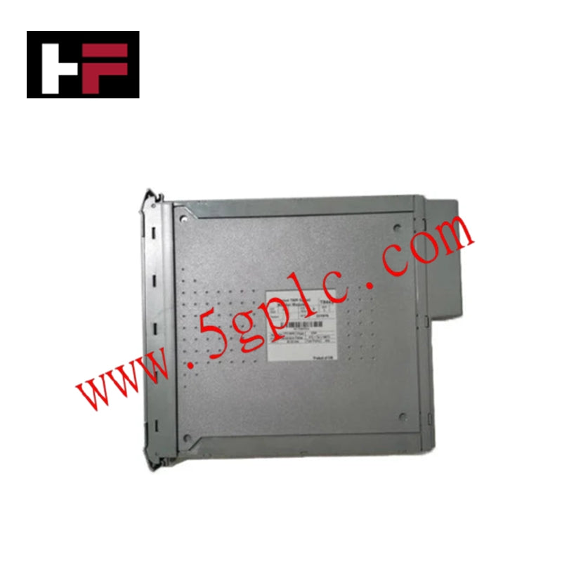
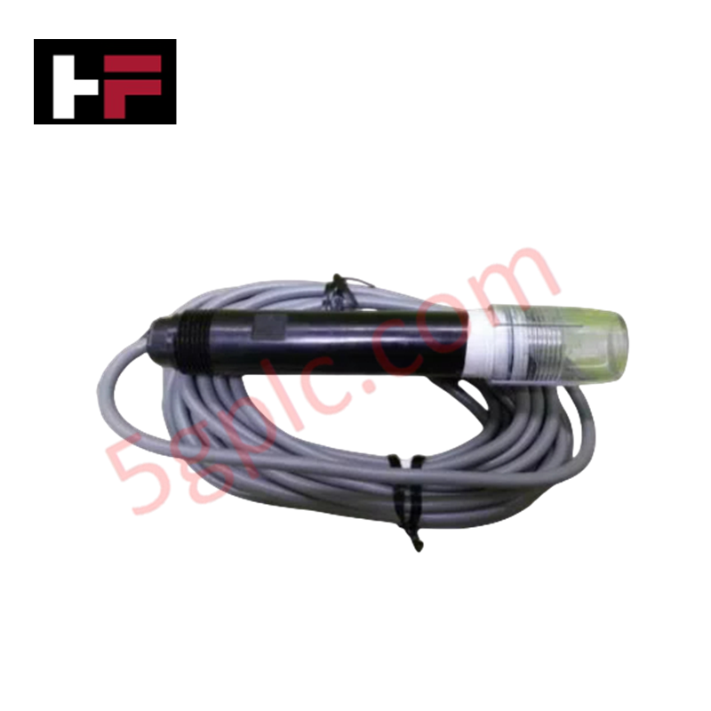
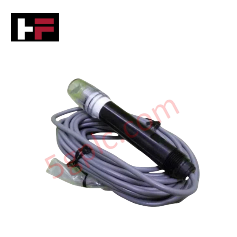
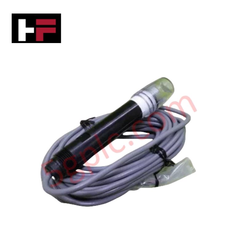
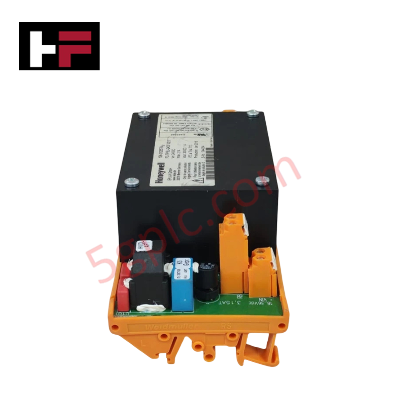
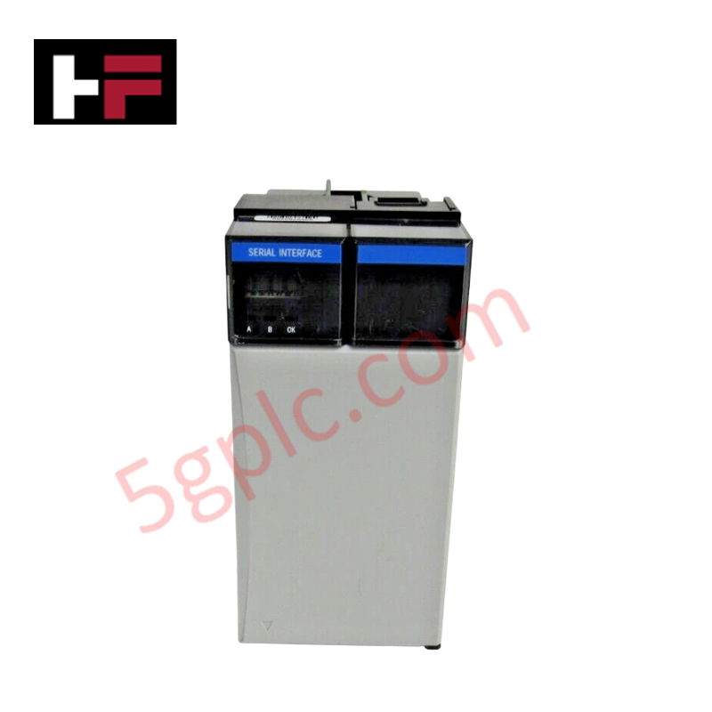
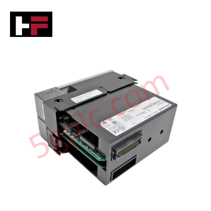
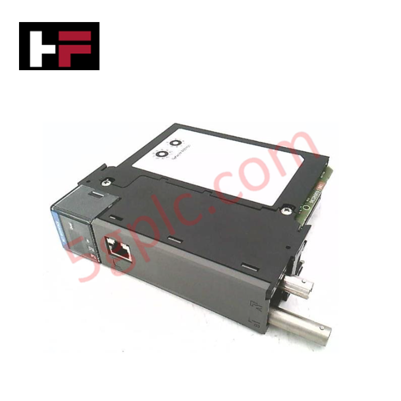
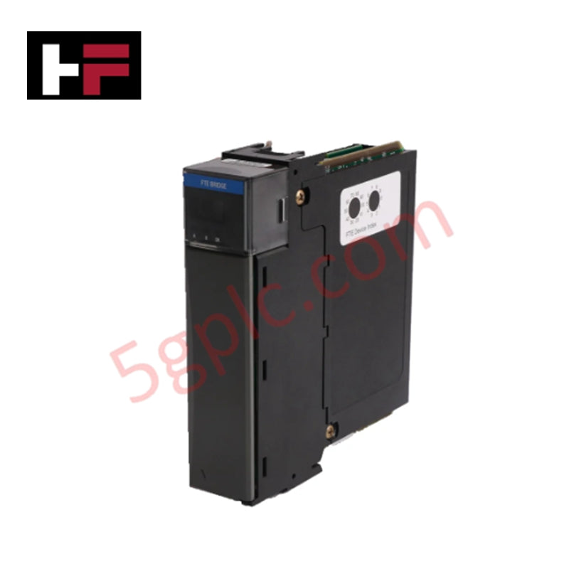
The Honeywell 51451326-504, also cataloged as the 51451326-504 Low Temperature Probe, operates as a dedicated hardware component for direct thermal signal measurement and RTD sensor interface execution within Honeywell DCS control platforms.
Hardware Specifications
| Parameter | Specification |
|---|---|
| Model | 51451326-504 |
| Brand | Honeywell |
| Origin | USA |
| Weight | 0.9 kg |
| Dimensions | 5 cm x 14.5 cm x 20 cm |
| Operating Temp | Standard cryogenic/low-temperature sensing range (-200 to +100 deg C) |
| Power Consumption | Passive sensor element (loop excitation powered) |
| Sensor Type | Low-temperature probe assembly |
| Primary Application | Direct process temperature measurement for analog input channels |
Cold Junction Compensation & 4-20 mA Loop Interface Characteristics
Designed for precise low-temperature tracking across industrial process loops, the probe assembly integrates high-purity thermal element wiring to prevent reference resistance drift. Internal lead-wire balancing compensates for parasitic line resistance, preventing measurement inaccuracies across long cable runs back to the analog input card. When connected to Honeywell DCS temperature transmitters, cold junction compensation (CJC) algorithms and galvanic signal isolation maintain total loop accuracy and prevent ground loop noise from degrading millivolt-level signal conversion.
Frequently Asked Questions
Q: Does this low temperature probe require external power to operate?
A: No, the probe utilizes passive sensing element technology and derives its operating excitation directly from the connected DCS analog temperature input channel or field transmitter loop.
Q: How is lead resistance compensation managed for long wiring runs to the I/O terminal block?
A: The probe supports standard 3-wire or 4-wire resistance temperature detector (RTD) configurations, allowing the controller input module to actively eliminate line-resistance voltage drops.
Q: What precautions should be taken to prevent thermowell moisture ingress at cryogenic temperatures?
A: Ensure the probe head assembly conduit connection is sealed with NPT thread sealant and sealed terminal glands to prevent moisture condensation inside the housing sheath.
Field Installation Guidelines
- Mount the probe assembly into the process thermowell, ensuring full mechanical engagement to maintain proper thermal conduction.
- Apply anti-seize compound to all stainless steel thermowell threads prior to hand-tightening to at least 5 full NPT thread engagements.
- Route sensor lead wiring in grounded metal conduit separated from high-voltage AC cables to eliminate electromagnetic noise coupling.
- Terminate signal wires according to 3-wire or 4-wire schematics at the field termination assembly (FTA) or junction box.
- Ground the cable shield braiding at a single point on the DCS system earth bus bar to eliminate ground loop currents.
Additional Information
- 100% Genuine Parts: All products are original and authentic, ensuring reliable industrial performance.
- 30-Day Refund Guarantee: Return any in-stock item within 30 days in original, unopened packaging for a full refund (excluding shipping and fees).
- 12-Month Warranty: Covers defects in materials or workmanship; excludes misuse, normal wear, or unauthorized modifications.
- Worldwide Shipping: We ship via USPS, UPS, FedEx, and DHL. Delivery times vary by country and may be subject to customs or import fees.
- Support & Contact: Technical and warranty assistance is available anytime. Contact us here: Contact.
- Purchase Guidance: Check product specifications and compatibility carefully before ordering to ensure proper application.


Tech & Buying Guide

Mastering VFD Braking Theory and Mechanical Brake Sequencing in Industrial Automation
In industrial automation, variable frequency drives (VFDs) regulate motor speed and torque across manufacturing plants and material handling systems. However, certain heavy-duty applications experience external loads that can rotate the motor shaft without an active command. For instance, gravity pulls loads downward in unanchored hoisting equipment. Therefore, engineers integrate mechanical brakes with VFD logic to maintain absolute safety and prevent structural damage or personnel injury during shutdowns.

Optimizing Tank Level Control Using Proportional Algorithms in PLC Systems
Industrial automation engineers frequently encounter liquid level regulation challenges across diverse process plants. Traditional ON-OFF control mechanisms often disrupt system stability due to abrupt actuator switching. Therefore, upgrading to closed-loop architectures like proportional control yields smoother responses. In a typical PLC environment, such as Siemens TIA Portal, engineers utilize closed-loop feedback to minimize process errors without requiring full PID complexity.

Understanding Why Your PLC Enters Stop Mode: Causes and Troubleshooting
In industrial automation, programmable logic controllers (PLCs) serve as the core intelligence of modern factory automation and distributed control systems (DCS). Understanding how a PLC transitions between modes is vital for maintenance engineers. Typically, a PLC operates across four primary modes: Run, Stop, Start-Up, and Hold. When power is applied, the system immediately boots into Stop mode before initiating the Start-Up sequence. If the controller encounters a critical error during execution, it automatically reverts to Stop mode to prevent equipment damage. Therefore, monitoring these state transitions helps technicians maintain high system availability.