













Product Details
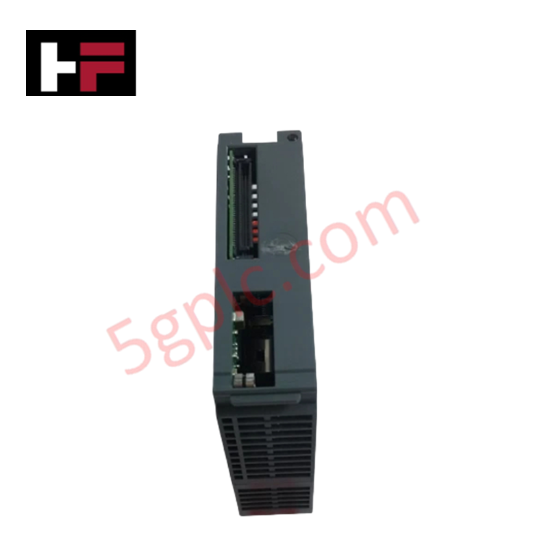
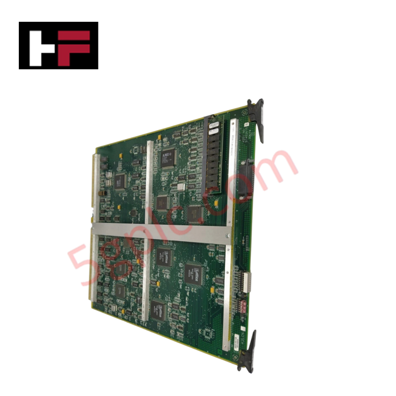
The Honeywell 2MLR-DBSF, also cataloged as the 2MLR-DBSF Expansion Driver Module, operates as a dedicated hardware component for expansion base optical fiber signal execution within MasterLogic-200 automation platforms.
Hardware Specifications
| Parameter | Specification |
|---|---|
| Model | 2MLR-DBSF |
| Brand | Honeywell |
| Origin | South Korea |
| Operating Temp | -10 to +60 deg C |
| Power Consumption | Backplane 5 VDC supply load |
| Product Type | Expansion Driver Module |
| Transmission Media | Optical fiber |
| Maximum Distance | 2 km between expansion bases |
| Cable Specification | 62.5/125 Multi-mode Fiber |
| Connector Type | LC-type (Lucent Connector) |
| Return Loss | Over 45 dB |
Channel Isolation and Optical Signal Attenuation Characteristics
The 2MLR-DBSF interface module employs optical fiber transmission circuits to provide physical signal isolation and transient noise rejection across remote expansion base racks. By using multi-mode fiber media, the hardware eliminates ground loops and cross-channel electrical interference over distances up to 2 km. Optical transceiver stages utilize LC-type connectors engineered to maintain high return loss performance exceeding 45 dB, preventing signal reflections from disrupting high-speed backplane packet execution during continuous process automation cycles.
Frequently Asked Questions
Q: What optical fiber specifications are required for connecting expansion bases via the 2MLR-DBSF?
A: The module requires 62.5/125 multi-mode optical fiber fitted with LC-type connectors to maintain link budget integrity up to 2 km.
Q: Is hot-swapping supported for the 2MLR-DBSF module during active system communication?
A: Insertion or removal must be performed only when the expansion rack base is powered down or configured according to MasterLogic live-insertion safety guidelines to avoid interrupting optical link integrity.
Field Installation Guidelines
- Align the 2MLR-DBSF module with the dedicated expansion slot on the MasterLogic base unit and press firmly until the locking mechanism engages.
- Ensure LC optical fiber connectors are thoroughly cleaned with optical lint-free wipes prior to insertion into the module transceivers.
- Observe minimum bend radius requirements for 62.5/125 multi-mode fiber cabling during tray routing to prevent signal attenuation and mechanical stress.
- Verify that the total optical link distance between connected expansion bases does not exceed the maximum rating of 2 km.
Additional Information
- 100% Genuine Parts: All products are original and authentic, ensuring reliable industrial performance.
- 30-Day Refund Guarantee: Return any in-stock item within 30 days in original, unopened packaging for a full refund (excluding shipping and fees).
- 12-Month Warranty: Covers defects in materials or workmanship; excludes misuse, normal wear, or unauthorized modifications.
- Worldwide Shipping: We ship via USPS, UPS, FedEx, and DHL. Delivery times vary by country and may be subject to customs or import fees.
- Support & Contact: Technical and warranty assistance is available anytime. Contact us here: Contact.
- Purchase Guidance: Check product specifications and compatibility carefully before ordering to ensure proper application.




Tech & Buying Guide

FAT vs SAT in Industrial Control Systems: Key Differences and Execution Guide
Industrial control system deployment relies on strict verification protocols to guarantee operational safety, system stability, and regulatory compliance. Commissioning complex Programmable Logic Controller (PLC) racks, Distributed Control Systems (DCS), and Safety Instrumented Systems (SIS) requires two critical milestones: the Factory Acceptance Test (FAT) and the Site Acceptance Test (SAT). Both procedures validate that system automation meets design specifications, but they occur at different stages of project execution and target distinct operational risks.

Hub vs Switch vs Router in Industrial Automation Architecture
Modern factory automation relies on reliable industrial networking infrastructure to exchange real-time field data across operational technology systems. Engineers often encounter networking hardware like hubs, switches, and routers when integrating Programmable Logic Controllers, Distributed Control Systems, and SCADA monitoring nodes. Although these devices share physical ports, they operate at different layers of the Open Systems Interconnection reference model and deliver distinct traffic management capabilities.

Marshalling Cabinet Preventive Maintenance: Essential Healthiness Checks for PLC, DCS, and ESD Systems
Marshalling cabinets serve as the vital interface between field instrumentation and control room electronics in modern process facilities. Regular preventive maintenance of these cabinets ensures signal integrity across programmable logic controllers (PLCs), distributed control systems (DCS), and emergency shutdown (ESD) networks. System technicians must execute structured inspection protocols to mitigate environmental risks, identify loose wiring, and maintain continuous operational readiness.