


Product Details
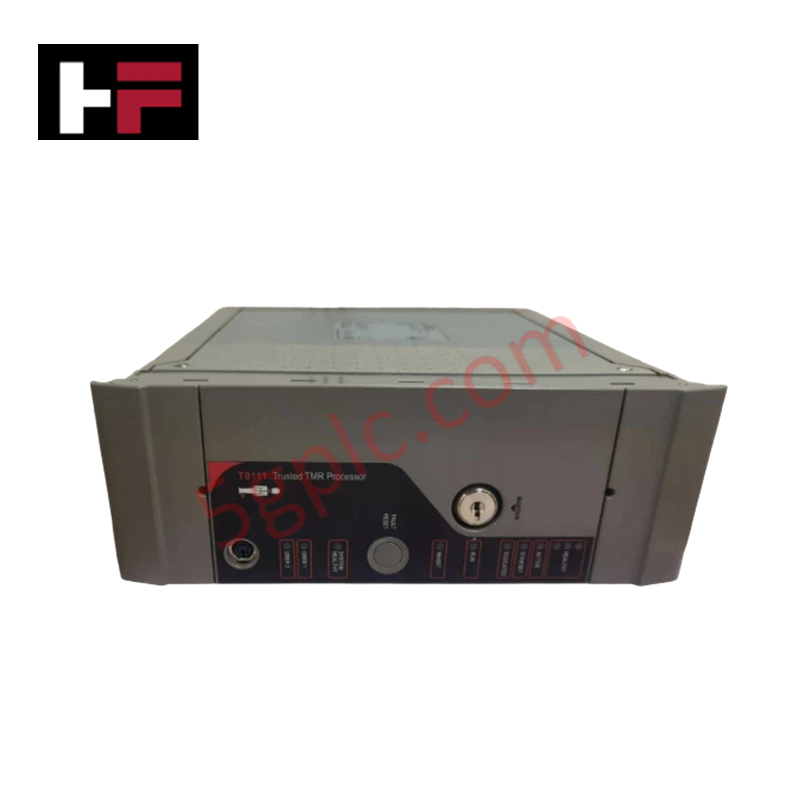
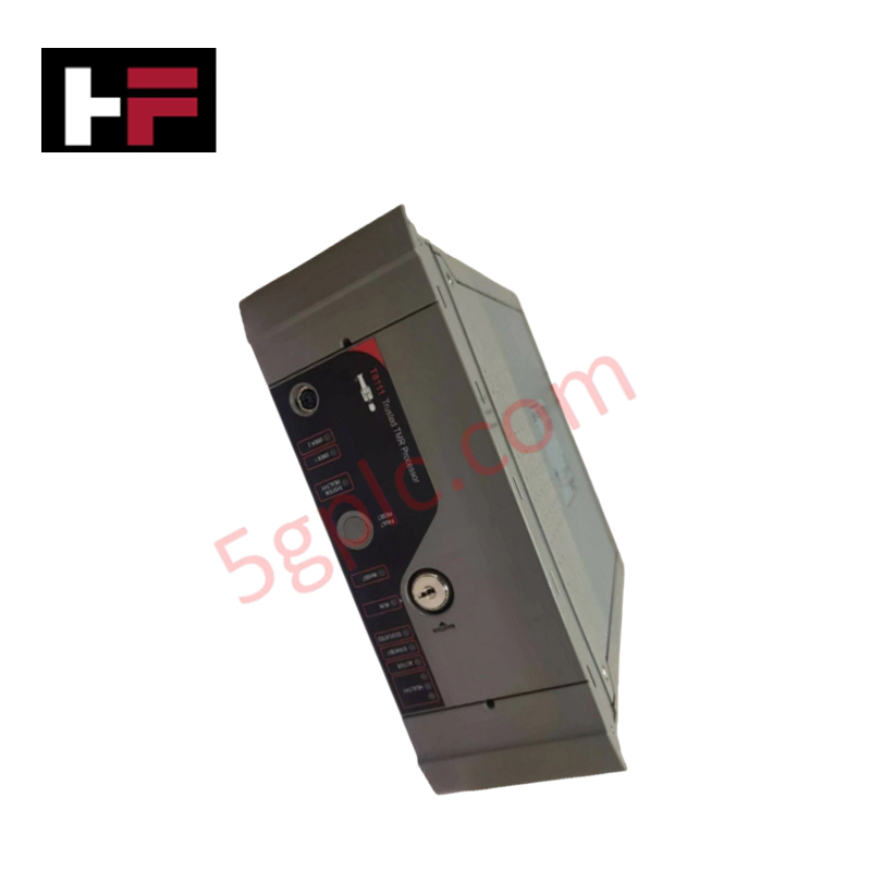
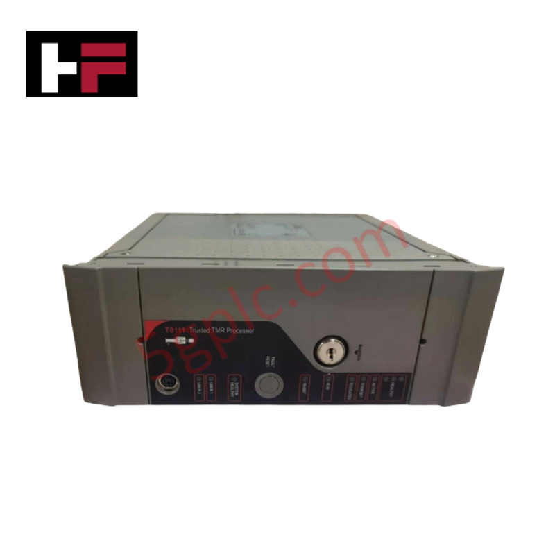
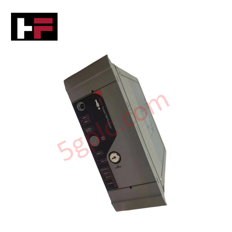
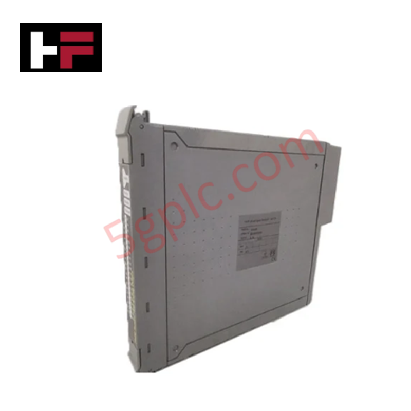
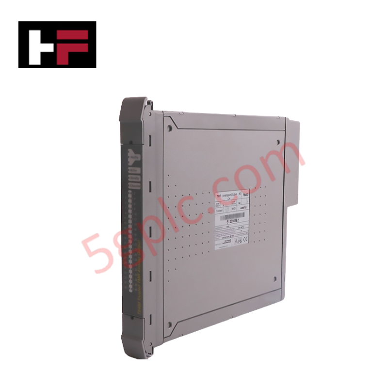
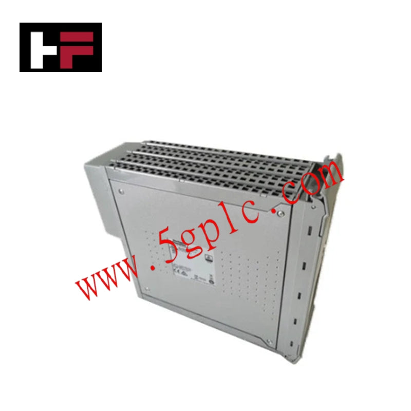
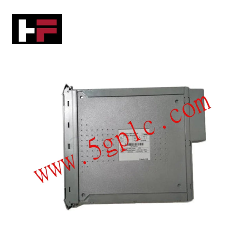
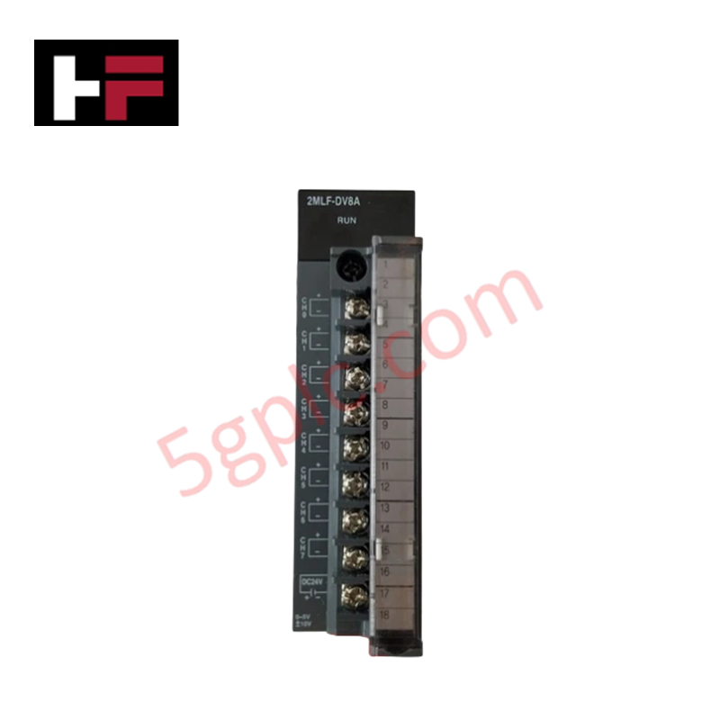
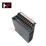
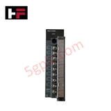
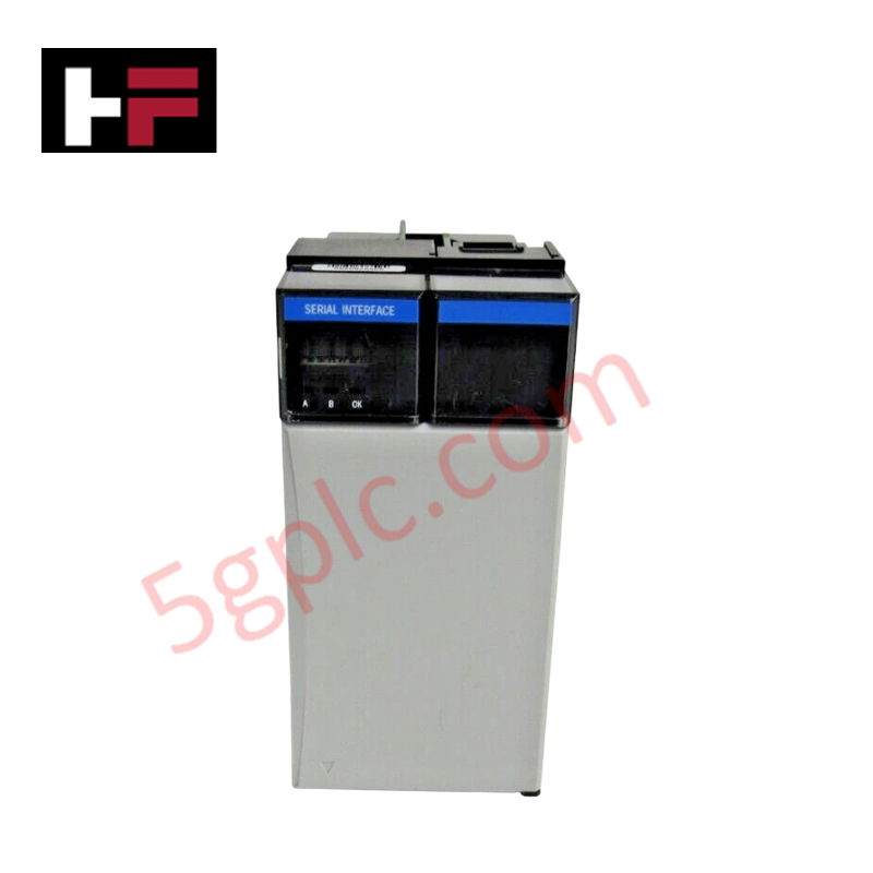
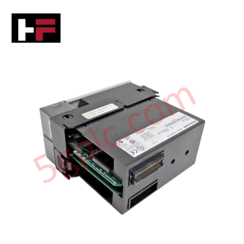
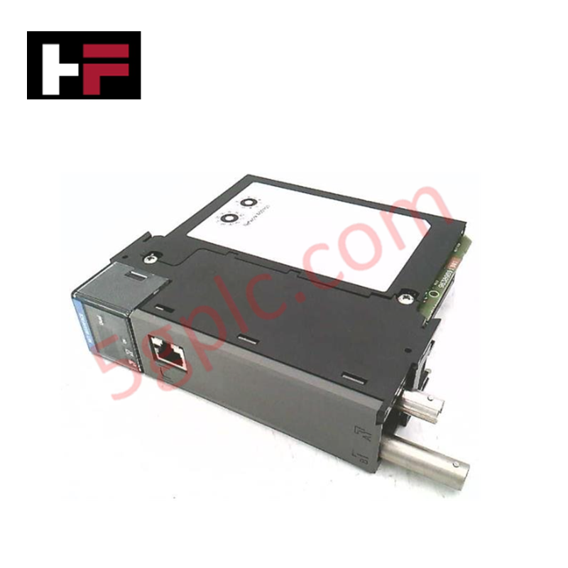
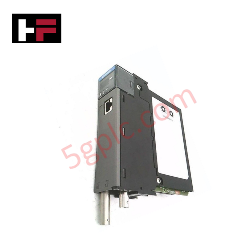
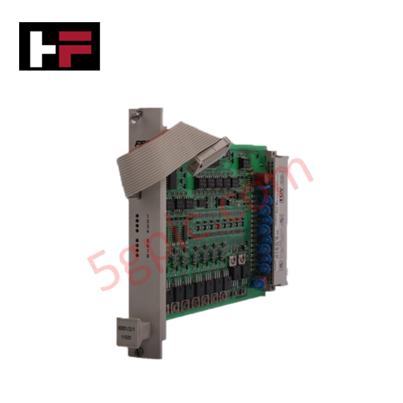
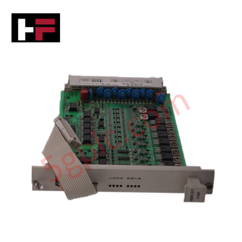
The Honeywell 2MLF-DV8A, also cataloged as the 2MLF-DV8A Analog Output Module, operates as a dedicated hardware component for multi-channel voltage signal generation within MasterLogic-200 platforms.
Hardware Specifications
| Parameter | Specification |
|---|---|
| Model | 2MLF-DV8A |
| Brand | Honeywell |
| Origin | South Korea |
| Operating Temp | 0 to 55 deg C |
| Power Consumption | Standard MasterLogic-200 backplane bus load |
| Output Type | Voltage source |
| Number of Channels | 8 channels |
| Output Signal Ranges | 0 to 10 VDC, -10 to +10 VDC, 0 to 5 VDC, 1 to 5 VDC |
| Load Resistance | 1 kohm or greater |
| Range Configuration | Software selectable via application parameters |
Channel Isolation & Signal Conditioning
The 2MLF-DV8A drives 8 independent analog voltage loops across multi-range control configurations. Channel-to-channel isolation and backplane decoupling protect digital logic from external field transient surges. Internal digital-to-analog converters (DAC) process internal PLC bus register data into stable voltage commands (0 to 10 VDC, -10 to +10 VDC, 0 to 5 VDC, or 1 to 5 VDC) with loop stability maintained when tied to field loads of 1 kohm or greater.
Frequently Asked Questions
Q: How are individual output ranges configured on the 2MLF-DV8A module?
A: Output ranges (0 to 10 VDC, -10 to +10 VDC, 0 to 5 VDC, 1 to 5 VDC) are configured per channel via software application parameters within the PLC programming environment.
Q: What is the minimum allowable load resistance for the voltage output loops?
A: Connected field devices or actuator inputs must maintain a load resistance of 1 kohm or greater to prevent output current saturation.
Q: Can the module be inserted into the rack while the backplane is powered?
A: Power to the base rack must be isolated prior to module insertion or removal to prevent physical hardware damage to backplane bus contacts.
Field Installation Guidelines
- Turn off all main power sources to the PLC base unit before installing or removing the 2MLF-DV8A module from the backplane rack.
- Ensure field signal cables connected to the voltage output terminals use shielded twisted-pair conductors to minimize electromagnetic noise coupling.
- Terminate individual cable shields directly to the cabinet ground bar at a single point to prevent ground loop currents across signal references.
- Align module base edge connectors with the backplane slot guide channels and push firmly until the top and bottom retention latches engage completely.
Additional Information
- 100% Genuine Parts: All products are original and authentic, ensuring reliable industrial performance.
- 30-Day Refund Guarantee: Return any in-stock item within 30 days in original, unopened packaging for a full refund (excluding shipping and fees).
- 12-Month Warranty: Covers defects in materials or workmanship; excludes misuse, normal wear, or unauthorized modifications.
- Worldwide Shipping: We ship via USPS, UPS, FedEx, and DHL. Delivery times vary by country and may be subject to customs or import fees.
- Support & Contact: Technical and warranty assistance is available anytime. Contact us here: Contact.
- Purchase Guidance: Check product specifications and compatibility carefully before ordering to ensure proper application.


Tech & Buying Guide

Comprehensive Guide to Servo Motor Drive Control Techniques in Industrial Automation
Precision motion control systems drive high-throughput manufacturing across modern industrial automation environments. Unlike standard induction motors running on basic variable frequency drives, servo motor systems deliver sub-millimeter positioning accuracy and fast dynamic response.

Industrial PLC Communication Protocols: A Comprehensive Engineering Guide
Modern factory automation relies heavily on industrial communication protocols to connect field instruments, controllers, and enterprise networks. Beyond traditional hardwired I/O, robust communication networks allow programmable logic controllers (PLCs) to exchange telemetry, diagnostic data, and control commands efficiently across complex architectures.

Understanding PLC Digital Output Types: Relay, Transistor, and Triac Explained
Programmable Logic Controllers (PLCs) form the backbone of modern industrial automation systems. They interface directly with field devices such as solenoid valves, indicator lights, motor starters, and interposing relays. Selecting the correct digital output module ensures high system availability and long hardware service life.