










Product Details
Product Overview
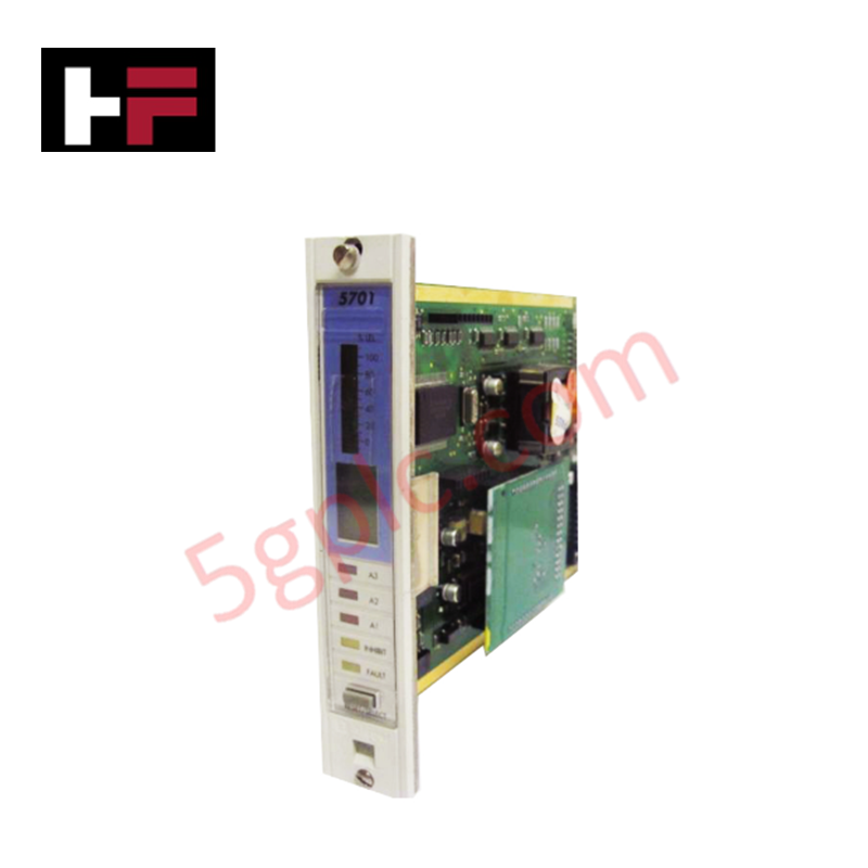
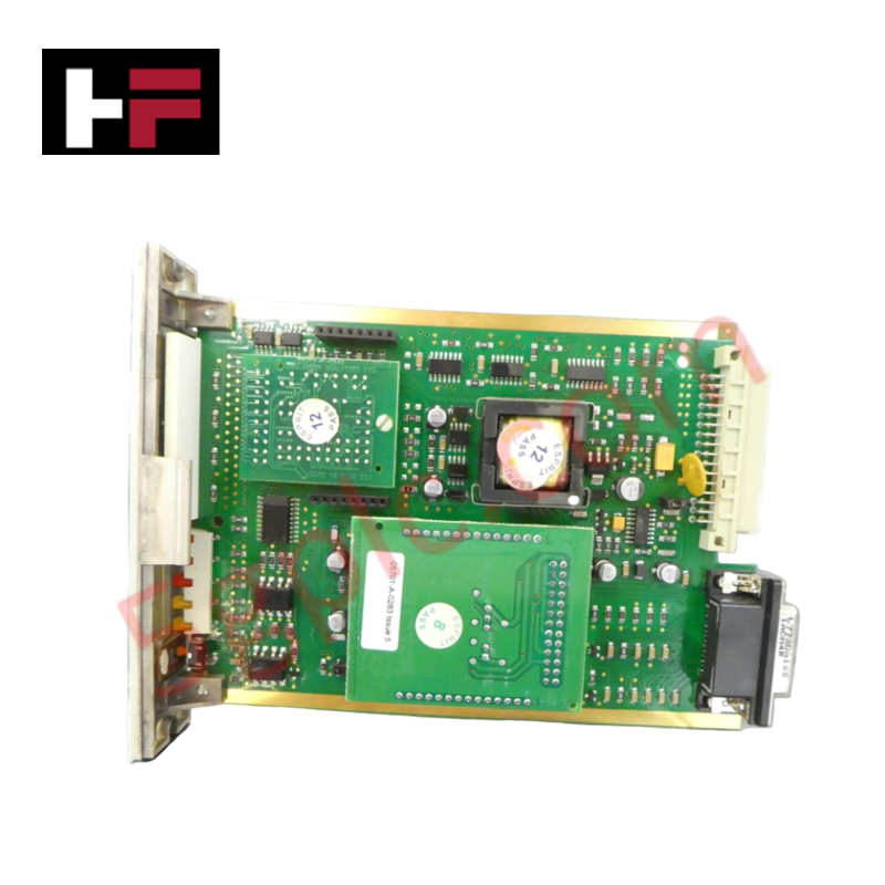
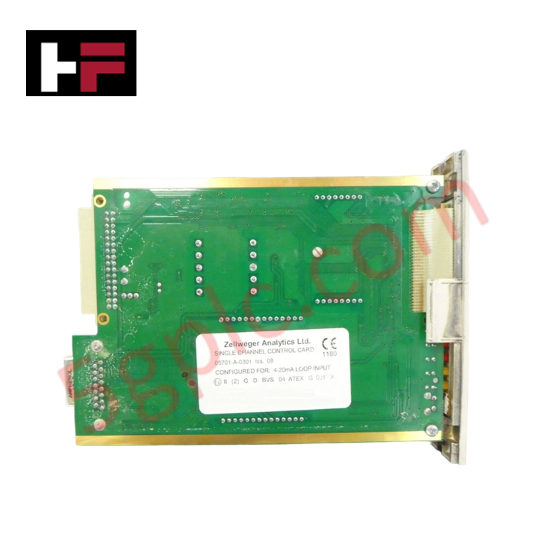
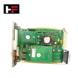
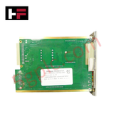
The Honeywell 05701-A-0301 functions as a high-precision, single-channel monitoring interface within the industry-standard System 57 gas detection framework. This dedicated card processes standard 4-20mA or catalytic bead sensor inputs from field-mounted gas detectors, translating raw telemetry into real-time visual readouts and discrete safety relay triggers.
We supply this card exclusively as a 100% brand new, original factory-sealed component to guarantee uncompromised loop integrity, precise alarm thresholds, and full compliance with industrial plant safety mandates.
Technical Specifications
The following table details the physical, electrical, and display specifications of the control module:
| Parameter | Performance & Hardware Specifications |
| Manufacturer | Honeywell |
| Product Number | 05701-A-0301 |
| Product Type | Single Channel Control Card (System 57 Series) |
| Input Signal Compatibility | 4 - 20 mA Current Loop / Catalytic Bead Sensors |
| DC Power Supply Range | 18V to 32V DC |
| Power Consumption | Catalytic: 3.75W (includes sensor) / 4-20mA: 3.25W (typical) |
| Display Architecture | Four-Part Liquid Display (25-segment analog bar, 4-char digital, 4-char message, icon section) |
| Status LEDs | A1, A2, A3 Gas Alarms; Fault; Inhibit |
| Interface Buttons | Dual-function Alarm Reset / Card Select |
| Alarm Set Point Resolution | 1% of Full Scale Deflection (fsd) steps |
| Electronic Drift Profile | Less than ±2% over a 6-month operating window |
| Physical Dimensions | 17.0 cm x 2.5 cm x 11.2 cm |
| Net Weight | 0.165 Kg (0.36 lbs) |
Engineering Advantages
-
Maximizes Density in Multi-Point Gas Systems: The ultra-slim 2.5 cm card width allows engineering teams to pack dozens of independent gas monitoring channels into a standard 19-inch rack. This tight form factor resolves the physical spatial constraints commonly found in offshore control rooms and localized analyzer houses.
-
Eliminates Calibration Fatigue via Ultra-Low Drift: The refined internal analog-to-digital circuitry restricts electronic drift to under ±2% every six months. This long-term stability reduces the need for frequent trim adjustments, keeping safety loops online and lowering overall plant maintenance hours.
-
Provides Instant Multi-Tiered Hazard Diagnostics: The unique four-part liquid crystal display combines an instantaneous 25-segment analog bar graph with precise four-character digital readouts. Operators identify developing gas leaks from across the floor via the dedicated A1, A2, and A3 alarm LEDs before the gas concentrations reach critical hazardous levels.
FAQs
-
Can I use the 05701-A-0301 card with both toxic gas transmitters and combustible gas sensors?
Yes. The card accepts both direct catalytic bead inputs (typical for combustible gases) and standard 4-20mA loops (typical for toxic gas or oxygen transmitters). You configure the input source selection on the card to match your specific field device.
-
What precautions should I take during installation to prevent damage to the card?
Always isolate the rack power supply before inserting or removing the card. Because the 05701-A-0301 uses sensitive CMOS electronics, technicians must wear a grounded electrostatic discharge (ESD) wrist strap during handling to prevent latent static damage to the microprocessor.
-
How do the "Fault" and "Inhibit" LEDs assist during field sensor calibration?
The "Inhibit" LED illuminates when you place the card into maintenance mode, which temporarily freezes the output safety relays. This prevents the card from triggering false plant-wide shutdowns while you apply calibration gas to the field sensor. The "Fault" LED activates instantly if the card detects an open or short circuit on the incoming 4-20mA signal lines.
Additional Information
- 100% Genuine Parts: All products are original and authentic, ensuring reliable industrial performance.
- 30-Day Refund Guarantee: Return any in-stock item within 30 days in original, unopened packaging for a full refund (excluding shipping and fees).
- 12-Month Warranty: Covers defects in materials or workmanship; excludes misuse, normal wear, or unauthorized modifications.
- Worldwide Shipping: We ship via USPS, UPS, FedEx, and DHL. Delivery times vary by country and may be subject to customs or import fees.
- Support & Contact: Technical and warranty assistance is available anytime. Contact us here: Contact.
- Purchase Guidance: Check product specifications and compatibility carefully before ordering to ensure proper application.




Tech & Buying Guide

Demystifying the DDE Protocol in Legacy Industrial Automation Systems
Modern control systems rely heavily on seamless interprocess communication to exchange operational data between software programs. Microsoft first introduced the Dynamic Data Exchange (DDE) protocol in 1987 to enable real-time data sharing. In factory automation, DDE served as an early bridge between control software and Windows desktop applications. Therefore, understanding DDE mechanics provides crucial insights into how legacy industrial networks established software-level connectivity.

Demystifying CPU Communication Ports in Siemens PLC Architectures
Industrial automation relies heavily on robust data exchange between devices. Without seamless connectivity, field instruments, network switches, human-machine interfaces, and programmable logic controllers cannot coordinate effectively. Therefore, understanding the various CPU communication ports available in Siemens hardware ensures efficient factory automation design and seamless system integration.

Mastering the Siemens PLC Scan Cycle: How the CPU Executes Automation Programs
Industrial automation relies heavily on programmable logic controllers (PLCs) to manage complex manufacturing processes. Many engineers dive straight into programming without mastering the underlying architecture. However, understanding how a PLC CPU executes a program ensures reliable system design. Therefore, mastering the scan cycle optimizes both performance and troubleshooting in modern control systems.