


Detalles del producto
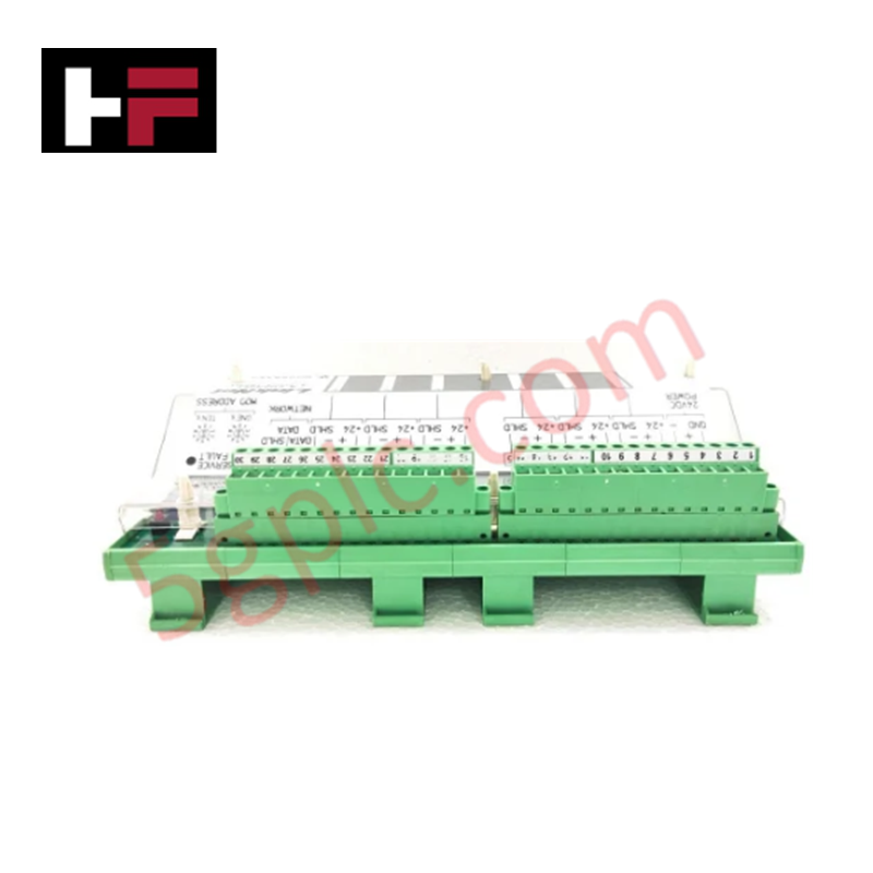
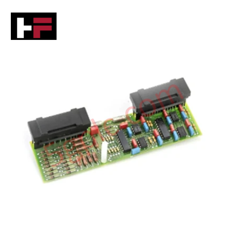
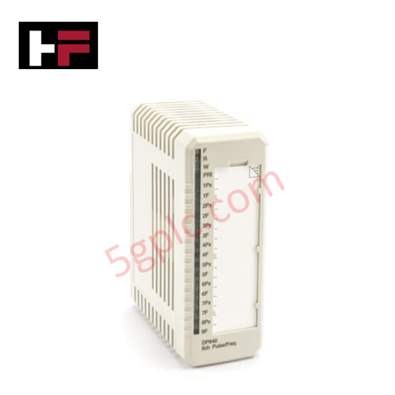
Configurado para la adquisición distribuida de señales analógicas en arquitecturas de control de turbinas LinkNet, el Woodward 9905-970 (módulo de entrada LinkNet 9905-970) proporciona una ejecución física/eléctrica directa de la conversión de la señal del sensor.
Especificaciones del hardware
| Parámetro | Especificación |
|---|---|
| Modelo | 9905-970 |
| Marca | Woodward |
| Dimensiones | 14 x 11 x 4 pulgadas |
| Temperatura de funcionamiento | -40 a 85 °C |
| Consumo de energía | Entrada de 24 VCC |
| Impedancia de la señal | 33 K Ohms |
| Protección transitoria | 900 VCC |
Respuesta de retroalimentación del lazo del actuador
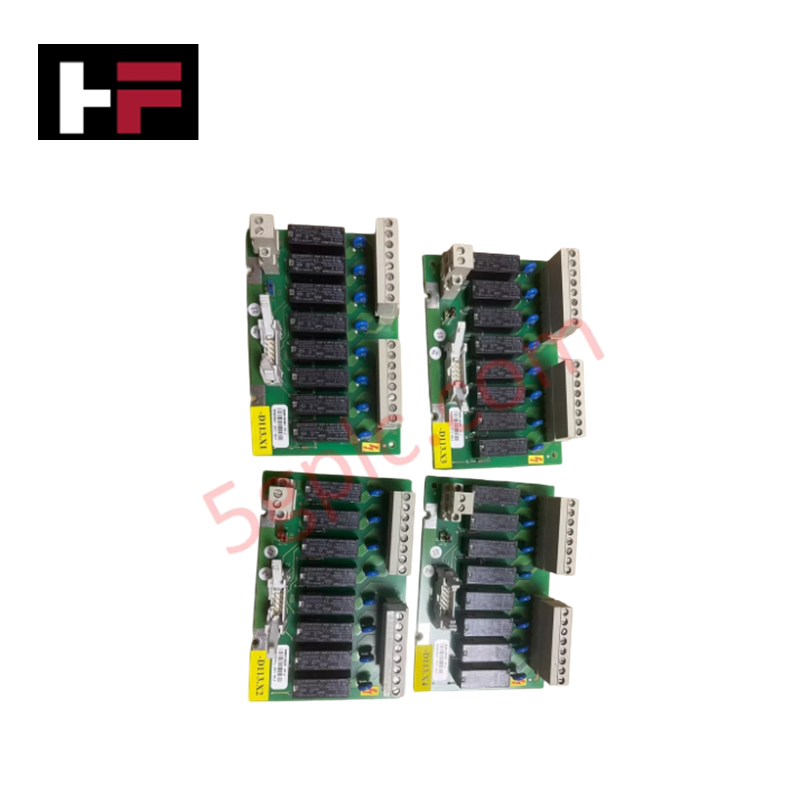
El módulo 9905-970 funciona como un nodo remoto dentro de la red de E/S distribuida LinkNet, traduciendo las entradas de los sensores de campo en paquetes de datos para el controlador anfitrión. La impedancia de entrada de 33 K Ohms del módulo está diseñada para minimizar los efectos de carga en la instrumentación de procesos sensible. Los circuitos internos incluyen protección transitoria de hasta 900 VCC para salvaguardar el módulo contra sobretensiones eléctricas comunes. Para mantener un rendimiento estable de la retroalimentación del lazo del actuador, el cableado de campo debe enrutarse para evitar interferencias electromagnéticas de alta energía, y la dirección del módulo debe sincronizarse correctamente con la configuración del grupo de velocidad de la red en el controlador maestro.
Preguntas frecuentes
P: ¿Cuál es la función principal de la pantalla LED de 24 caracteres de este módulo?
R: La pantalla LED integrada proporciona indicación de estado local para el módulo, incluida la actividad del canal y la notificación de condiciones de error, lo que facilita el diagnóstico durante la puesta en marcha en campo.
P: ¿Es este módulo capaz de mantener el funcionamiento a la temperatura máxima especificada de 85 °C?
R: El módulo está clasificado para funcionar hasta 85 °C. Sin embargo, asegúrese de que la ubicación de montaje del armario de control proporcione suficiente convección natural o forzada para evitar la acumulación de calor localizada que podría exceder la temperatura de funcionamiento nominal en la superficie del módulo.
Pautas de instalación en campo
- Montaje: Fije el módulo dentro de la carcasa del panel utilizando los orificios de montaje provistos. Asegúrese de que las dimensiones de 14 x 11 x 4 pulgadas permitan un espacio adecuado para el cableado de comunicación y señal.
- Cableado: Utilice cableado de par trenzado blindado para la conexión troncal de LinkNet. Conecte los cables de señal a los bloques de terminales, asegurándose de que se mantengan las polaridades según el diagrama de cableado del sistema.
- Blindaje y toma de tierra: Conecte los blindajes de los cables al terminal de tierra designado en el panel de control para mitigar el ruido inducido y garantizar la integridad de los datos en la red distribuida.
- Configuración: Establezca los interruptores internos de direccionamiento de nodos para que coincidan con la configuración programada en el software del controlador anfitrión antes de aplicar energía.
- Validación: Después de la instalación, verifique el estado de la pantalla LED para confirmar que el módulo ha establecido comunicación con el tronco de la red.
Información adicional
- 100% Piezas Originales: Todos los productos son originales y auténticos, garantizando un rendimiento industrial confiable.
- Garantía de Reembolso de 30 Días: Devuelva cualquier artículo en stock dentro de los 30 días en su embalaje original y sin abrir para un reembolso completo (excluyendo envío y tarifas).
- Garantía de 12 Meses: Cubre defectos en materiales o mano de obra; excluye mal uso, desgaste normal o modificaciones no autorizadas.
- Envío Mundial: Enviamos vía USPS, UPS, FedEx y DHL. Los tiempos de entrega varían según el país y pueden estar sujetos a aduanas o tarifas de importación.
- Soporte y Contacto: Asistencia técnica y de garantía disponible en cualquier momento. Contáctenos aquí: Contacto.
- Guía de Compra: Verifique cuidadosamente las especificaciones y compatibilidad del producto antes de ordenar para asegurar la aplicación correcta.
Guía de Tecnología y Compras

Comprendiendo los contactos secos en el cableado de PLC: una guía de automatización industrial
Dominar los principios de conmutación de contactos es esencial para paneles de control fiables. Los dispositivos de campo y los PLC interactúan a través de contactos secos o húmedos. Esta guía técnica examina la mecánica de los contactos secos, explora sus arquitecturas de cableado y evalúa sus principales ventajas en la automatización industrial.

Lista de control definitiva para la puesta en marcha de sistemas de automatización industrial: Una guía de ingeniería
La puesta en marcha es la fase más decisiva de un proyecto de automatización industrial, ya que transforma el hardware y el software de control en una instalación operativa. Las pruebas exhaustivas evitan costosos retrasos en la puesta en marcha y generan confianza en el cliente. Esta guía cubre listas de verificación esenciales, estándares eléctricos y mejores prácticas.

Sistemas de Automatización Redundantes: Arquitectura Central, Valor de Negocio y Ventajas Técnicas
Las interrupciones no planificadas representan una gran amenaza financiera para la fabricación por procesos. Para evitar interrupciones costosas, los ingenieros implementan arquitecturas redundantes de PLC y DCS que garantizan el funcionamiento continuo cuando el hardware falla. Esta guía técnica explora los principios de redundancia, los nodos críticos del sistema y escenarios del mundo real.