


Produktdetails
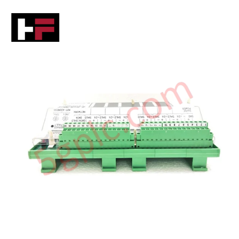
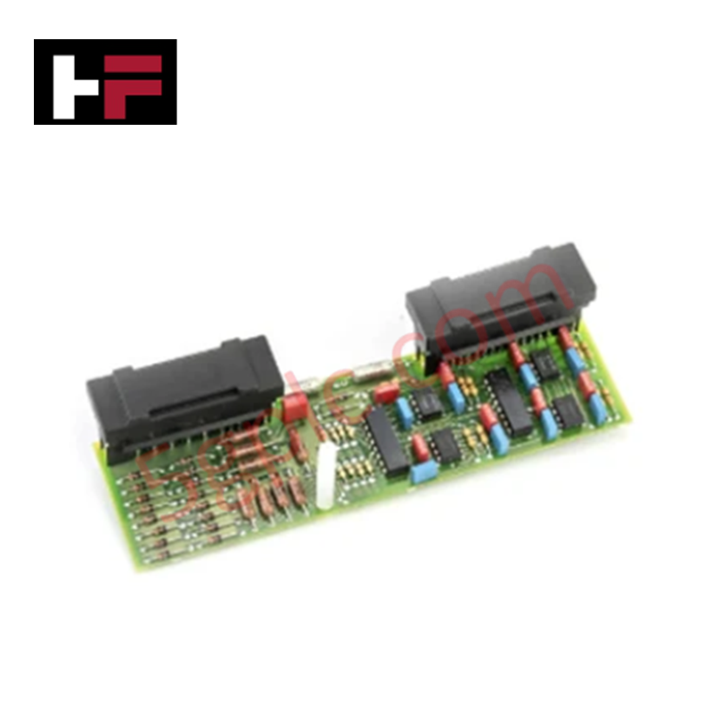
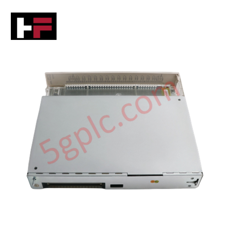
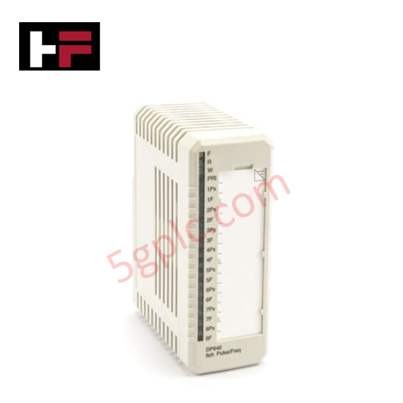
Konfiguriert für die verteilte analoge Signalerfassung in LinkNet-Turbinensteuerungsarchitekturen, bietet das Woodward 9905-970 (9905-970 LinkNet Eingabemodul) die direkte physikalisch/elektrische Umsetzung der Sensorsignalkonvertierung.
Hardware-Spezifikationen
| Parameter | Spezifikation |
|---|---|
| Modell | 9905-970 |
| Marke | Woodward |
| Abmessungen | 14 x 11 x 4 Zoll |
| Betriebstemperatur | -40 bis 85 °C |
| Stromverbrauch | 24 VDC Eingang |
| Signalimpedanz | 33 kOhm |
| Überspannungsschutz | 900 VDC |
Rückmeldung des Aktuatorschleifen-Feedbacks
Das 9905-970 Modul fungiert als Remote-Knoten innerhalb des LinkNet verteilten I/O-Netzwerks und wandelt Feldeingangssignale von Sensoren in Datenpakete für den Host-Controller um. Die Eingangsimpedanz von 33 kOhm ist so ausgelegt, dass sie Belastungseffekte auf empfindliche Prozessinstrumente minimiert. Die interne Schaltung beinhaltet einen Überspannungsschutz bis 900 VDC, um das Modul vor üblichen elektrischen Spannungsspitzen zu schützen. Um eine stabile Rückmeldung der Aktuatorschleife zu gewährleisten, muss die Feldverkabelung so verlegt werden, dass hochenergetische elektromagnetische Störungen vermieden werden, und die Moduladresse muss korrekt mit den Netzwerkrate-Gruppeneinstellungen im Master-Controller synchronisiert sein.
Häufig gestellte Fragen
F: Was ist die Hauptfunktion der 24-stelligen LED-Anzeige an diesem Modul?
A: Die integrierte LED-Anzeige bietet eine lokale Statusanzeige für das Modul, einschließlich Kanalaktivität und Fehlerberichterstattung, was die Diagnose während der Inbetriebnahme vor Ort erleichtert.
F: Ist dieses Modul in der Lage, den Betrieb bei der maximal angegebenen Temperatur von 85 °C aufrechtzuerhalten?
A: Das Modul ist für den Betrieb bis zu 85 °C ausgelegt. Stellen Sie jedoch sicher, dass der Montageort im Schaltschrank ausreichende natürliche oder erzwungene Konvektion bietet, um eine lokale Wärmeentwicklung zu vermeiden, die die zulässige Betriebstemperatur an der Moduloberfläche überschreiten könnte.
Richtlinien für die Feldinstallation
- Montage: Befestigen Sie das Modul im Schaltschrankgehäuse mit den vorgesehenen Befestigungslöchern. Stellen Sie sicher, dass die Abmessungen von 14 x 11 x 4 Zoll ausreichend Freiraum für Kommunikations- und Signalkabel bieten.
- Verdrahtung: Verwenden Sie geschirmte verdrillte Adern für die LinkNet-Stammleitung. Schließen Sie die Signalleitungen an die Klemmenblöcke an und achten Sie darauf, die Polaritäten gemäß dem Systemverdrahtungsplan einzuhalten.
- Abschirmung und Erdung: Schließen Sie die Kabelschirmungen am vorgesehenen Erdungsklemmenanschluss im Schaltschrank an, um induzierte Störungen zu minimieren und die Datenintegrität im verteilten Netzwerk sicherzustellen.
- Konfiguration: Stellen Sie die internen Adresswahlschalter so ein, dass sie mit der im Host-Controller-Software programmierten Konfiguration übereinstimmen, bevor Sie die Stromversorgung einschalten.
- Validierung: Überprüfen Sie nach der Installation den Status der LED-Anzeige, um zu bestätigen, dass das Modul erfolgreich die Kommunikation mit dem Netzwerkstamm hergestellt hat.
Zusätzliche Informationen
- 100% Originalteile: Alle Produkte sind original und authentisch, was eine zuverlässige industrielle Leistung gewährleistet.
- 30-Tage Rückgabegarantie: Rückgabe aller vorrätigen Artikel innerhalb von 30 Tagen in der originalen, ungeöffneten Verpackung für eine volle Rückerstattung (ohne Versandkosten und Gebühren).
- 12 Monate Garantie: Deckt Material- oder Verarbeitungsfehler ab; schließt Missbrauch, normalen Verschleiß oder unautorisierte Änderungen aus.
- Weltweiter Versand: Wir versenden über USPS, UPS, FedEx und DHL. Die Lieferzeiten variieren je nach Land und können Zoll- oder Einfuhrgebühren unterliegen.
- Support & Kontakt: Technische und Garantieunterstützung ist jederzeit verfügbar. Kontaktieren Sie uns hier: Kontakt.
- Kaufberatung: Überprüfen Sie vor der Bestellung sorgfältig die Produktspezifikationen und Kompatibilität, um eine korrekte Anwendung sicherzustellen.
Technik- & Kaufberatung

Verstehen von Trockenkontakten in der SPS-Verkabelung: Ein Leitfaden für die industrielle Automatisierung
Die Beherrschung der Prinzipien des Kontaktwechsels ist für zuverlässige Steuerungstafeln unerlässlich. Feldgeräte und SPS kommunizieren über trockene oder nasse Kontakte. Dieser technische Leitfaden untersucht die Funktionsweise trockener Kontakte, beleuchtet deren Verdrahtungsarchitekturen und bewertet ihre wichtigsten Vorteile in der industriellen Automatisierung.

Ultimative Inbetriebnahme-Checkliste für industrielle Automatisierungssysteme: Ein Ingenieurhandbuch
Die Inbetriebnahme ist die entscheidendste Phase eines Industrieautomatisierungsprojekts, bei der Steuerungshardware und -software in eine betriebsbereite Anlage verwandelt werden. Gründliche Tests verhindern kostspielige Verzögerungen beim Start und stärken das Vertrauen der Kunden. Dieser Leitfaden behandelt wichtige Checklisten, elektrische Normen und bewährte Verfahren.

Redundante Automatisierungssysteme: Kernarchitektur, Geschäftswert und technische Vorteile
Ungeplante Ausfallzeiten stellen eine erhebliche finanzielle Bedrohung für die Prozessfertigung dar. Um kostspielige Unterbrechungen zu vermeiden, setzen Ingenieure redundante PLC- und DCS-Architekturen ein, die einen kontinuierlichen Betrieb bei Hardwareausfällen gewährleisten. Dieser technische Leitfaden behandelt Redundanzprinzipien, kritische Systemknoten und praxisnahe Szenarien.