










Product Details
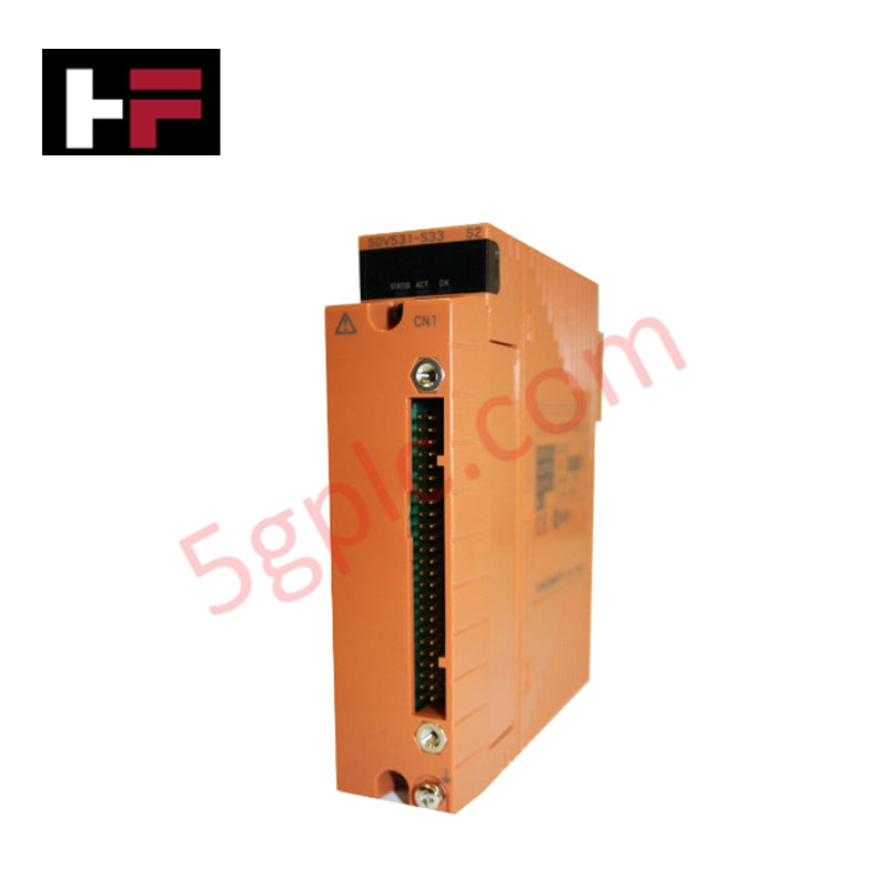
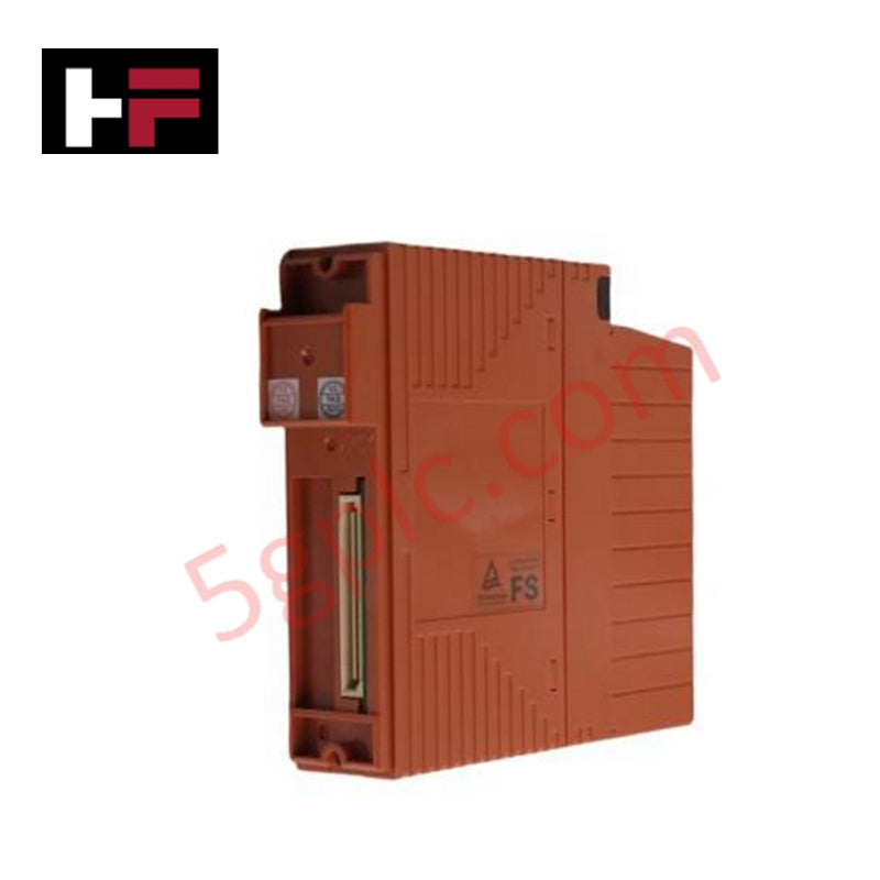
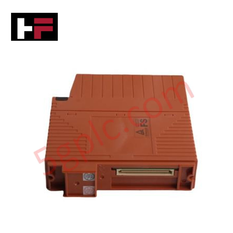
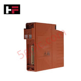
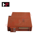
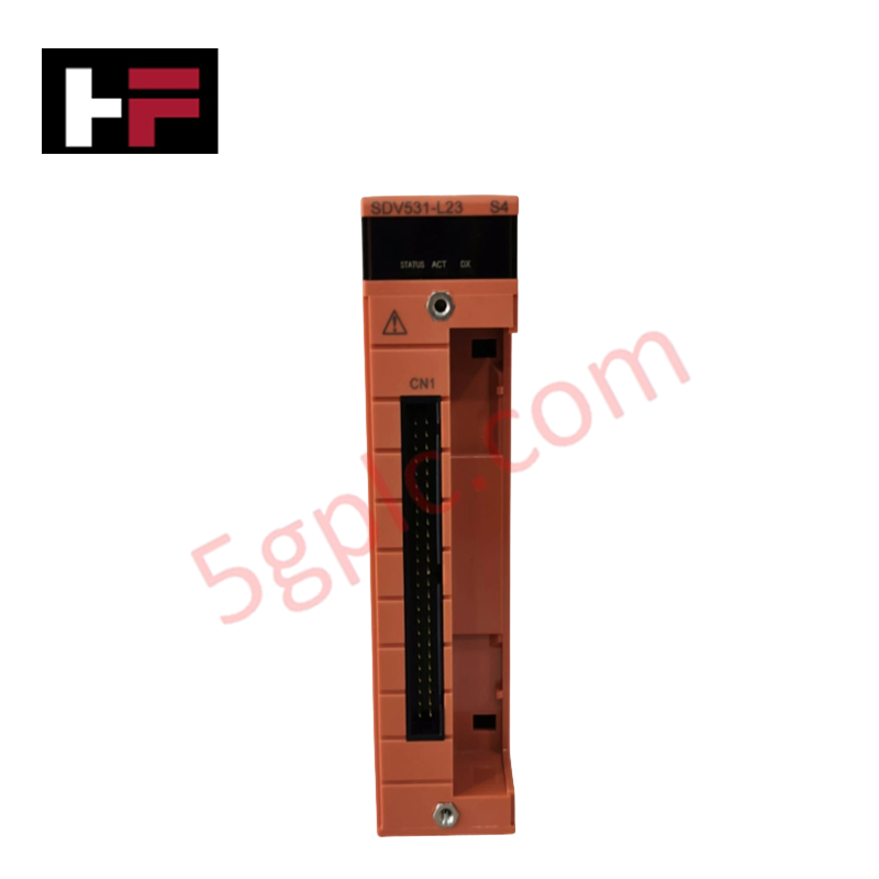
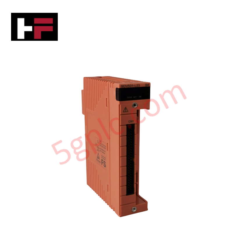
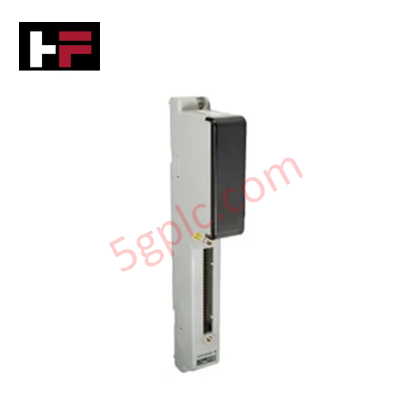
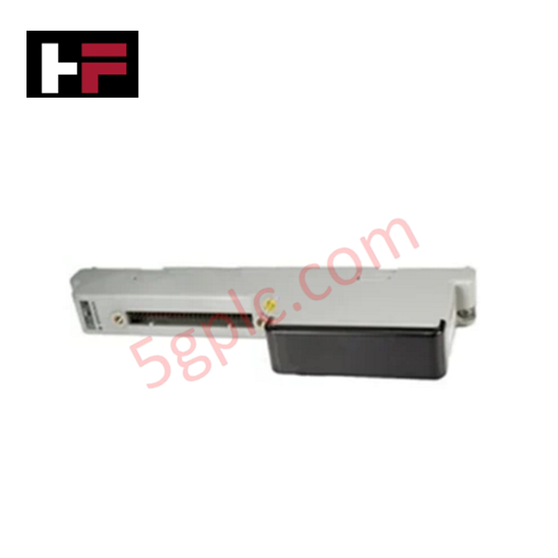
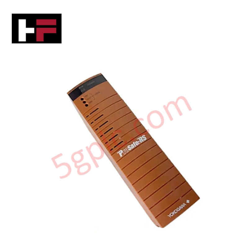
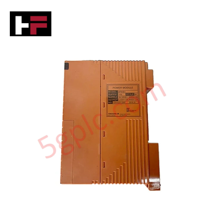
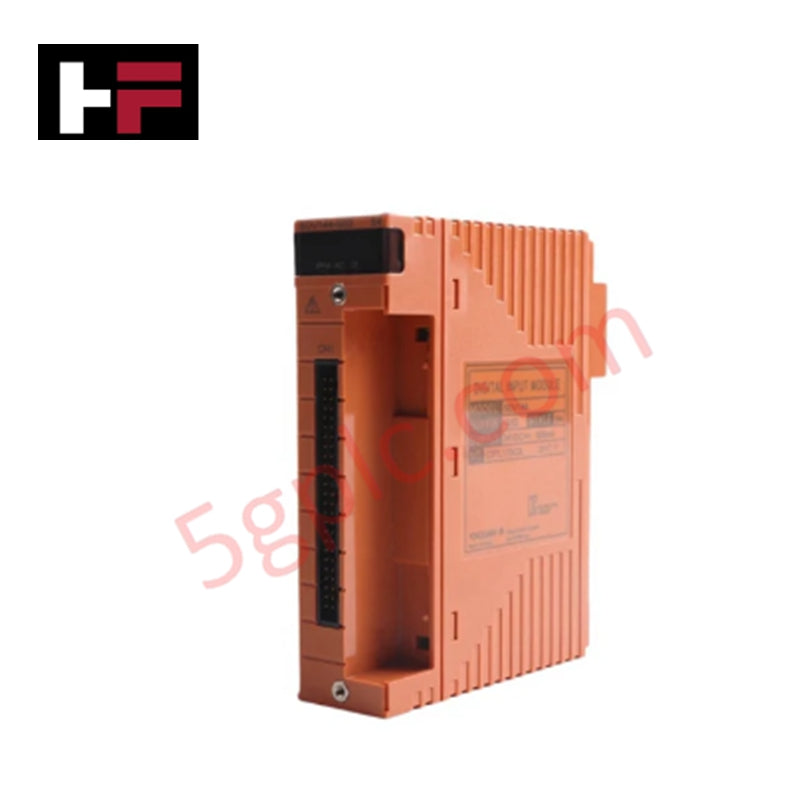
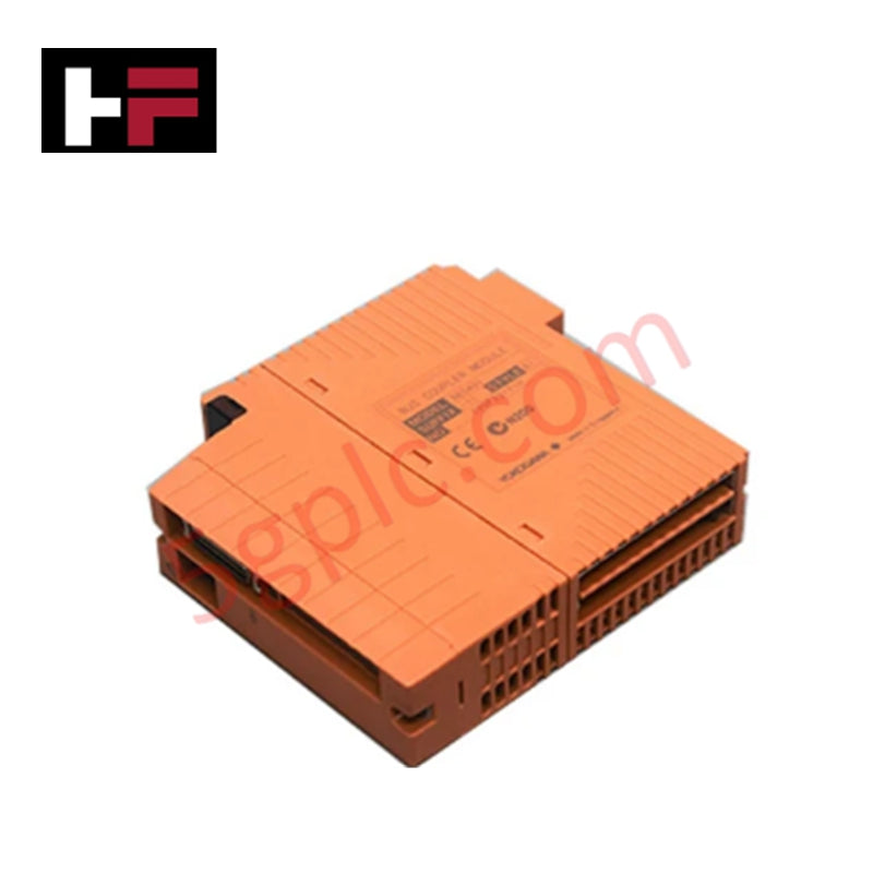
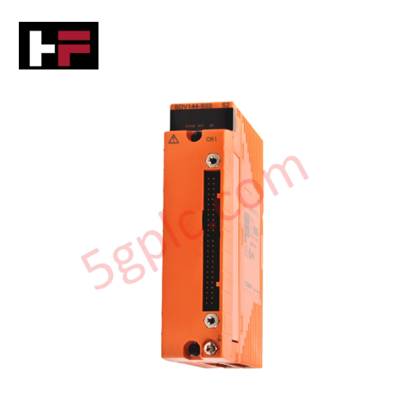
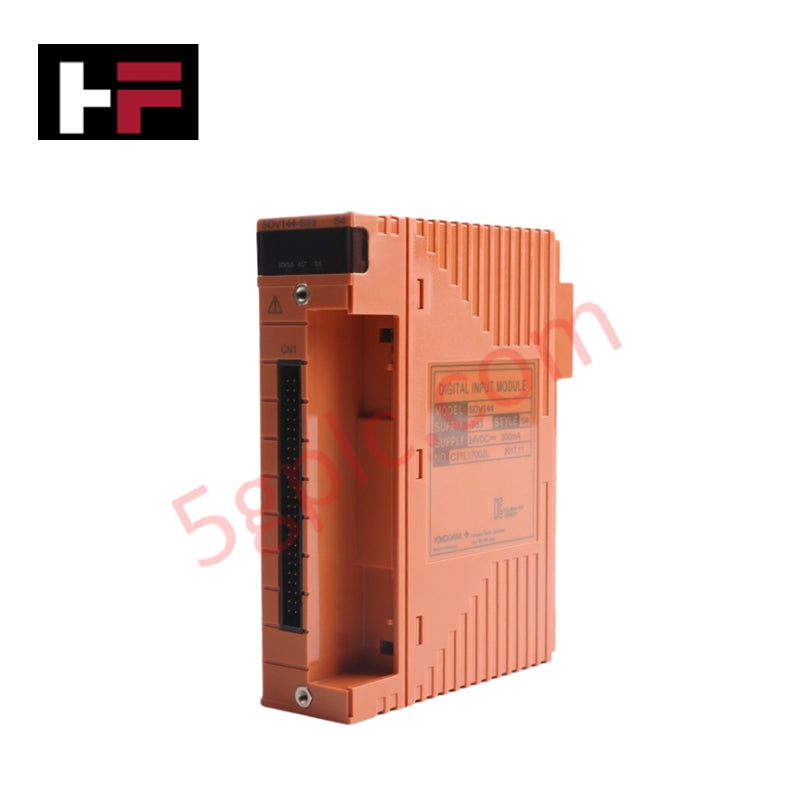
The Yokogawa SDV531-S13, also cataloged as the Yokogawa SDV531 Digital Output Module, operates as a dedicated hardware component for discrete field device actuation within ProSafe-RS safety instrumented system networks. The module executes high-current switching signals to final control elements while enforcing physical circuit separation and diagnostic verification loops under strict execution intervals.
Hardware Specifications
| Parameter | Specification |
|---|---|
| Model | SDV531-S13 |
| Brand | Yokogawa |
| Origin | Japan |
| Weight | 0.60 lbs |
| Dimensions | Standard Yokogawa I/O module form factor |
| Operating Temp | 0 to +60 deg C (Standard operation limits) |
| Power Consumption | 24 VDC bus powered |
| Module Type | Digital Output Module |
| Rated Output Voltage | 24 VDC |
| Maximum Output Current | 5.5 A |
| Lifecycle Classification | Revised to model SDV531-S23 |
| System Platform | ProSafe-RS |
Safety Control & Channel-to-Channel Isolation
The module architecture leverages galvanic channel-to-channel isolation barriers to isolate field-side electrical anomalies from the internal processing logic. By establishing discrete optical and transformer-coupled paths for individual signal loops, the hardware suppresses cross-talk and limits structural faults to single field termination lines. This preventative physical isolation layout matches the rigorous requirements of instrumented safety loops, maintaining high signal integrity for critical emergency shutdown elements and preventing multi-channel cascade failure modes.
Frequently Asked Questions
Q: What is the hardware replacement procedure given the model status revision to SDV531-S23?
A: When replacing an existing SDV531-S13 module, engineering teams must verify backplane compatibility and terminal block positioning before inserting the revised SDV531-S23 hardware. System configuration files and module parameters must be audited in the engineering station to ensure complete functional alignment with the updated hardware revision.
Q: Are hot-swap operations permitted for this digital output module during active system runtime?
A: Hot-swapping is permitted only if the specific safety loop configuration allows online maintenance without dropping the active field circuits into a fault state. The field side 24 VDC power lines must be monitored to ensure that removing the module does not cause inductive voltage spikes or disconnect adjacent redundant modules sharing the same power rail.
Field Installation Guidelines
- Shield Grounding and Drain Wire Termination: Field actuator cabling shields must be stripped, bundled, and terminated at the designated low-impedance system ground busbar inside the cabinet. Do not terminate the shield wire at both the module chassis and the field instrument to prevent the creation of ground loops that could distort logical diagnostics.
- Cabinet Thermal and Structural Integration: Secure the module firmly into its designated slots on the ProSafe-RS base plate to engage all backplane pins completely. Maintain unobstructed airflow through the cabinet ventilation slots to prevent localized heat accumulation from affecting the 5.5 A high-current output components.
- Inductive Load Suppression: When routing outputs to external inductive components such as large solenoid valves or mechanical interposing relays, fit external surge suppression diodes or RC snubbers directly across the field load terminals to prevent electrical arc damage across output circuits.
Additional Information
- 100% Genuine Parts: All products are original and authentic, ensuring reliable industrial performance.
- 30-Day Refund Guarantee: Return any in-stock item within 30 days in original, unopened packaging for a full refund (excluding shipping and fees).
- 12-Month Warranty: Covers defects in materials or workmanship; excludes misuse, normal wear, or unauthorized modifications.
- Worldwide Shipping: We ship via USPS, UPS, FedEx, and DHL. Delivery times vary by country and may be subject to customs or import fees.
- Support & Contact: Technical and warranty assistance is available anytime. Contact us here: Contact.
- Purchase Guidance: Check product specifications and compatibility carefully before ordering to ensure proper application.
Tech & Buying Guide

Understanding VFD Mechanical Brake Logic and Control in Industrial Automation
Variable Frequency Drives (VFDs) play a crucial role in modern industrial automation by controlling motor speed, torque, and acceleration. However, high-inertia loads and vertical lifting systems require precise mechanical braking logic to ensure operational safety and prevent equipment damage.

Why Programmable Logic Controllers Drop into Stop Mode: An Expert Analysis
Industrial automation systems rely heavily on Programmable Logic Controllers (PLCs) to maintain uninterrupted production. When a PLC unexpectedly shifts from Run to Stop mode, whole manufacturing lines stall.
As control systems evolve across modern factory automation, understanding the root causes of these interruptions helps engineers minimize costly downtime. This technical guide breaks down why PLCs trip into Stop mode and provides practical strategies to mitigate system faults.

Understanding Root Causes of Unplanned PLC Stop Mode in Industrial Automation
Modern Programmable Logic Controllers manage execution through distinct operational states: Run, Stop, Start-Up, and Hold. During power-up, a controller initializes memory registers within Stop mode before briefly transitioning to Start-Up mode. During this phase, internal self-diagnostics evaluate system integrity across hardware and user programs. If the controller detects no critical faults, it enters Run mode to execute the control program continuously. However, any severe system anomaly forces the CPU back into Stop mode immediately to prevent erratic machine behavior across the plant floor.