










Product Details
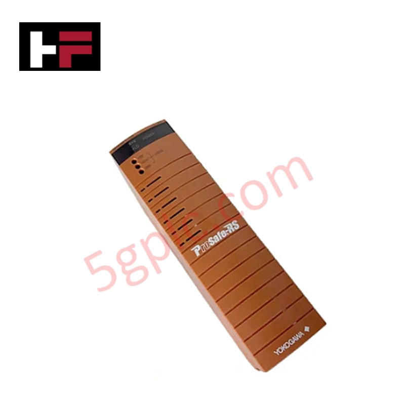
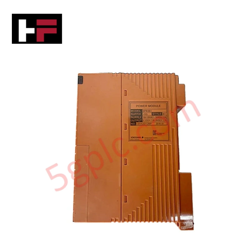
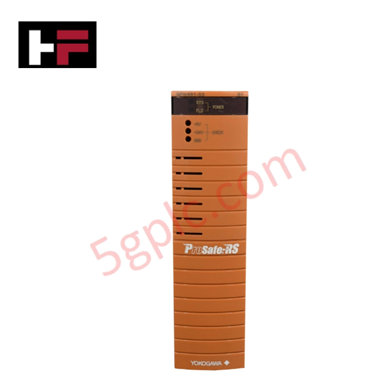
The Yokogawa SPW482-50 serves as the primary SPW482 Power Supply Module utilized to execute discrete power transformation and distribution across ProSafe-RS and CENTUM system platforms. Configured as a rack-mounted, plug-in assembly, the hardware converts high-voltage alternating current utility lines into a regulated 24 VDC secondary bus to energize adjacent field control units (FCU), FIO node units, or optical ESB bus repeater modules.
Suffix Breakdown & Model Matrix
- SPW482: Core power supply module base platform designation.
- -50: Suffix matrix variant specifying a 220 to 240 V AC nominal input range, 50 W output capacity, and standard integrated protection circuitry.
Hardware Specifications
| Parameter | Specification |
|---|---|
| Model | SPW482-50 |
| Brand | Yokogawa |
| Origin | Japan |
| Weight | ~1.4 kg |
| Dimensions | 44.45 x 264.2 x 186 mm |
| Operating Temp | 0 to 55 deg C |
| Power Consumption | ~230 VA maximum |
| Input Voltage | 220 to 240 V AC (+/-10%), 50/60 Hz |
| Output Voltage | 24 V DC (regulated) |
| Output Power | 50 W |
| Cooling Method | Natural convection (fanless design) |
| Protection Features | Overvoltage, overcurrent, short-circuit protection |
| Redundancy | Dual-redundant configuration supported via dual installation |
| Hot-Swap Capability | Yes, supports online replacement |
Process Control & Channel-to-Channel Isolation
The power subsystem architecture incorporates advanced isolation barriers to ensure distinct channel-to-channel isolation parameters between incoming utility feeds and local low-voltage DC buses. This topological segmentation isolates the high-voltage AC mains from the sensitive internal logic board, mitigating the propagation of common-mode voltage transients. Furthermore, this decoupling layout limits inductive cross-talk, protecting adjacent analog signal loops, including 4-20 mA HART loop protocol paths, from harmonic distortion or common-mode noise.
Frequently Asked Questions
Q: What are the engineering constraints regarding online hot-swap operations for this module?
A: Online hot-swapping is permitted only when the module is part of an active dual-redundant power configuration where two modules are installed in parallel. If a standalone single module configuration is extracted while energized, the power bus will collapse, resulting in immediate down-time of the associated FIO Node or FCU logic processing assembly.
Q: How does the module handle internal thermal dissipation without integrated fan assemblies?
A: The hardware utilizes a fanless natural convection profile. Heat distribution is dissipated directly through the integrated structural heat sinks and outer enclosure perforation patterns. This requires strict adherence to vertical rack clearance boundaries to ensure unobstructed passive airflow.
Field Installation Guidelines
- Chassis Insertion and Keying: Align the guide rails of the SPW482-50 with the base chassis slot before sliding the unit inward. Ensure the locking tabs snap completely into the backplane matrix to maintain a continuous, low-impedance electrical bond for the power terminals.
- AC Feed Separation and Routing: All incoming 220 to 240 V AC primary wiring must be physically segregated from low-voltage DC lines and communication trunk lines. Use dedicated non-combustible wireways to suppress electromagnetic coupling between line feeds and discrete signaling networks.
- Grounding and Shield Termination: Connect the rack frame ground terminal to the master plant copper instrumentation safety ground grid using a low-impedance conductor. All peripheral instrumentation drain wires must terminate at the centralized cabinet bus bar to prevent stray earth potential loops from inducing ripple voltages on the 24 VDC regulated output.
Additional Information
- 100% Genuine Parts: All products are original and authentic, ensuring reliable industrial performance.
- 30-Day Refund Guarantee: Return any in-stock item within 30 days in original, unopened packaging for a full refund (excluding shipping and fees).
- 12-Month Warranty: Covers defects in materials or workmanship; excludes misuse, normal wear, or unauthorized modifications.
- Worldwide Shipping: We ship via USPS, UPS, FedEx, and DHL. Delivery times vary by country and may be subject to customs or import fees.
- Support & Contact: Technical and warranty assistance is available anytime. Contact us here: Contact.
- Purchase Guidance: Check product specifications and compatibility carefully before ordering to ensure proper application.
Tech & Buying Guide

Understanding VFD Mechanical Brake Logic and Control in Industrial Automation
Variable Frequency Drives (VFDs) play a crucial role in modern industrial automation by controlling motor speed, torque, and acceleration. However, high-inertia loads and vertical lifting systems require precise mechanical braking logic to ensure operational safety and prevent equipment damage.

Why Programmable Logic Controllers Drop into Stop Mode: An Expert Analysis
Industrial automation systems rely heavily on Programmable Logic Controllers (PLCs) to maintain uninterrupted production. When a PLC unexpectedly shifts from Run to Stop mode, whole manufacturing lines stall.
As control systems evolve across modern factory automation, understanding the root causes of these interruptions helps engineers minimize costly downtime. This technical guide breaks down why PLCs trip into Stop mode and provides practical strategies to mitigate system faults.

Understanding Root Causes of Unplanned PLC Stop Mode in Industrial Automation
Modern Programmable Logic Controllers manage execution through distinct operational states: Run, Stop, Start-Up, and Hold. During power-up, a controller initializes memory registers within Stop mode before briefly transitioning to Start-Up mode. During this phase, internal self-diagnostics evaluate system integrity across hardware and user programs. If the controller detects no critical faults, it enters Run mode to execute the control program continuously. However, any severe system anomaly forces the CPU back into Stop mode immediately to prevent erratic machine behavior across the plant floor.