










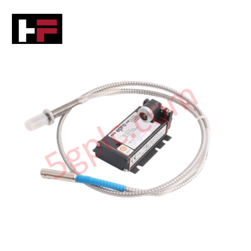


Product Details
The Emerson CON021+PR6423/10R-010-CN, also cataloged as the CON021+PR6423/10R-010-CN Eddy Current Sensor, operates as a dedicated hardware component for non-contact shaft vibration and dynamic displacement measurement within DCS and AMS 6500 Classic System platforms. The assembly combines an 8 mm probe tip configuration with signal conditioning circuitry to execute continuous real-time mechanical monitoring on rotating machinery shafts.
Hardware Specifications
| Parameter | Specification |
|---|---|
| Model | CON021+PR6423/10R-010-CN |
| Brand | Emerson |
| Origin | USA |
| Weight | 0.24 kg |
| Dimensions | 24.5 cm x 17 cm x 4 cm |
| Operating Temp | Extended industrial range |
| Power Consumption | Loop-powered via transmitter / monitoring module |
| Series | EPRO |
| Sensor Type | Non-contact eddy current proximity sensor |
| Probe Tip Diameter | 8 mm |
| System Compatibility | DCS, AMS 6500 Classic System |
| Data Interface | Ethernet router communication support |
| Mechanical Housing | Oil-resistant, high-temperature industrial casing |
Bently Nevada / VIBRO-METER Technical Characteristics
The non-contact measurement system relies on calibrated eddy-current probe scaling to convert physical gap variations into proportional electrical signals. Prior to commissioning, engineers conduct gap voltage validation targeting -10 VDC at the mechanical center of the probe linear range to ensure symmetrical peak-to-peak amplitude measurement. This calibrated voltage offset allows the transmitter to capture high-frequency rotor dynamics, including relative shaft vibration, thermal expansion growth, and radial position shifts. Differential driver architecture provides cross-talk suppression between adjacent probe channels mounted in close physical proximity on turbine bearing housings.
Frequently Asked Questions
Q: How is the physical gap voltage validated during mechanical installation of the PR6423/10R-010-CN probe?
A: With the target shaft stationary, adjust the probe thread depth until the DC voltage output at the CON021 signal conditioner measures -10 VDC, confirming the sensor is set at the center of its linear operating range.
Q: What precautions prevent cross-talk when mounting multiple eddy current probes in the same bearing housing?
A: Maintain the minimum recommended spatial separation between probe tips and ensure probe cables are routed in separate grounded metallic conduits to prevent electromagnetic signal cross-talk suppression failures.
Q: Does the CON021 converter require field calibration when changing the extension cable length?
A: Yes, total system length (probe, extension cable, and converter) must match the factory calibration curve to prevent errors in the eddy-current probe scaling output.
Field Installation Guidelines
- Inspect the target shaft surface to ensure it is clean and free of magnetic runout, scratches, or deep machining marks.
- Thread the 8 mm probe into the bearing housing mounting bracket until the probe tip approaches the target shaft face.
- Connect a digital multimeter to the signal conditioner monitor output terminals to measure the static DC gap voltage.
- Adjust the mechanical positioning of the probe until the multimeter reads the calibrated -10 VDC target setting, then tighten the external locknut.
- Connect extension cabling using the armor sleeve connectors and isolate the coaxial shield from machine ground at the probe end.
- Route signal wiring through dedicated instrument trays to the DCS or AMS 6500 monitoring rack, terminating shields at the single-point cabinet ground bar.
Additional Information
- 100% Genuine Parts: All products are original and authentic, ensuring reliable industrial performance.
- 30-Day Refund Guarantee: Return any in-stock item within 30 days in original, unopened packaging for a full refund (excluding shipping and fees).
- 12-Month Warranty: Covers defects in materials or workmanship; excludes misuse, normal wear, or unauthorized modifications.
- Worldwide Shipping: We ship via USPS, UPS, FedEx, and DHL. Delivery times vary by country and may be subject to customs or import fees.
- Support & Contact: Technical and warranty assistance is available anytime. Contact us here: Contact.
- Purchase Guidance: Check product specifications and compatibility carefully before ordering to ensure proper application.




Tech & Buying Guide

Why Programmable Logic Controllers Drop into Stop Mode: An Expert Analysis
Industrial automation systems rely heavily on Programmable Logic Controllers (PLCs) to maintain uninterrupted production. When a PLC unexpectedly shifts from Run to Stop mode, whole manufacturing lines stall.
As control systems evolve across modern factory automation, understanding the root causes of these interruptions helps engineers minimize costly downtime. This technical guide breaks down why PLCs trip into Stop mode and provides practical strategies to mitigate system faults.

Understanding Root Causes of Unplanned PLC Stop Mode in Industrial Automation
Modern Programmable Logic Controllers manage execution through distinct operational states: Run, Stop, Start-Up, and Hold. During power-up, a controller initializes memory registers within Stop mode before briefly transitioning to Start-Up mode. During this phase, internal self-diagnostics evaluate system integrity across hardware and user programs. If the controller detects no critical faults, it enters Run mode to execute the control program continuously. However, any severe system anomaly forces the CPU back into Stop mode immediately to prevent erratic machine behavior across the plant floor.

Human-Machine Interface Design: Essential Guide to HMI Selection, Visualization, and Control System Integration
Human-Machine Interfaces (HMIs) serve as the primary operational window into complex industrial automation systems. Modern HMIs convert raw machine data into clear graphical displays, enabling operators to oversee entire manufacturing processes in real time. Instead of relying on physical control panels full of hardwired switches, engineers program interactive screens using intuitive graphics, dynamic color coding, and responsive touch interfaces. Over my 15 years in control systems engineering, I have observed HMIs transform from basic display screens into sophisticated command centers that drive operational efficiency across DCS and PLC environments.