












Product Details
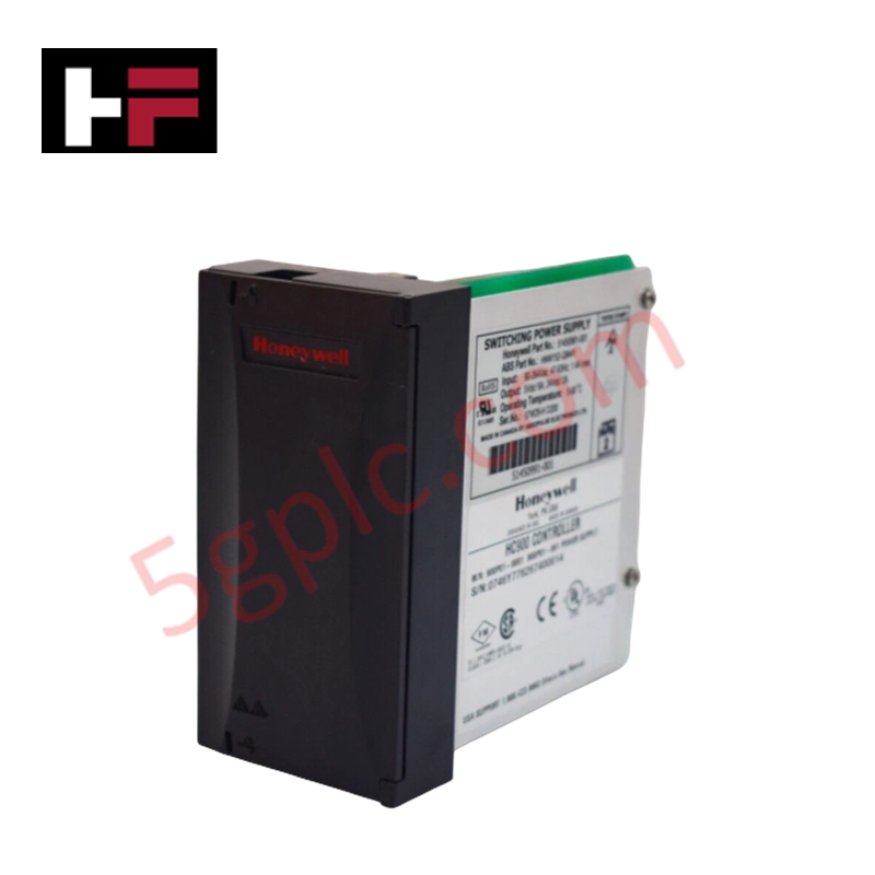
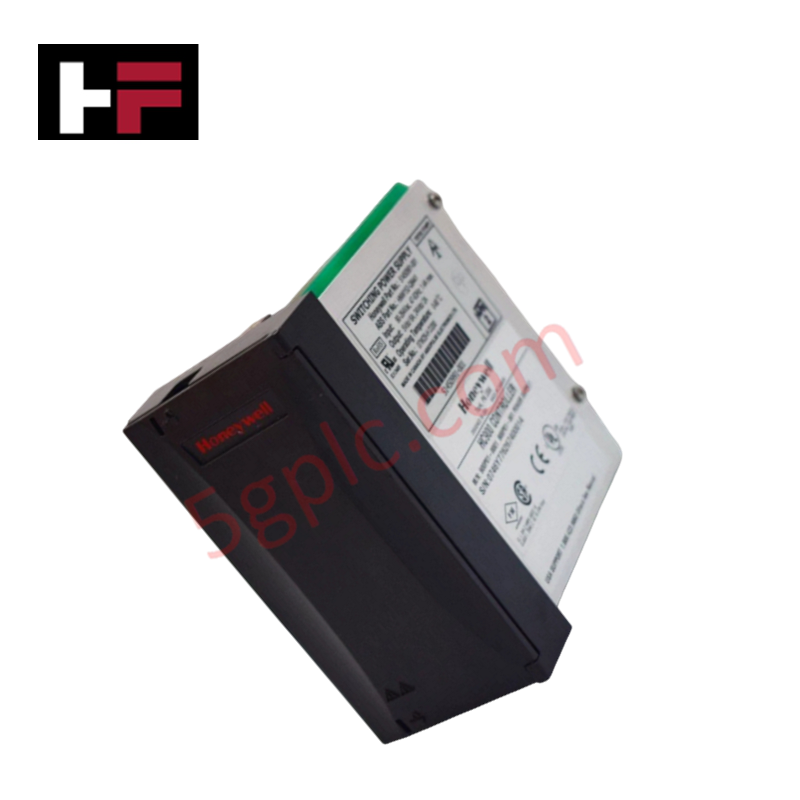
The Honeywell 51450991-001, also cataloged as the 51450991-001 Switching Power Supply, operates as a dedicated hardware component for direct AC-to-DC regulated power conversion within Honeywell controller hardware backplanes.
Hardware Specifications
| Parameter | Specification |
|---|---|
| Model | 51450991-001 |
| Brand | Honeywell |
| Origin | USA |
| Weight | 5.0 kg (Shipping) |
| Dimensions | Standard Controller Chassis Power Bay |
| Operating Temp | 0 to 60 deg C |
| Power Consumption | Input Current 1.4 A Maximum |
| Input Voltage | 90-264 VAC, 47-63 Hz |
| Output Voltage | 5 VDC / 24 VDC Dual Output |
| Output Current | 5 VDC at 6 A Maximum, 24 VDC at 2 A Maximum |
| Output Power | 58 W Total Continuous |
Channel Isolation & Loop Power Execution
The internal power conversion stage incorporates galvanically isolated transformer windings to decouple main AC lines from secondary logic rails. Integrated channel-to-channel isolation prevents line transients from corrupting 5 VDC processor logic and 24 VDC field transmitter loops. Built-in overvoltage and short-circuit protection circuits maintain stable output regulation across the 58 W total continuous load rating, ensuring ripple-free power distribution to adjacent DCS controller and I/O modules.
Frequently Asked Questions
Q: What are the input electrical specifications supported by this power supply unit?
A: The module accepts a wide-range AC input from 90 to 264 VAC at a line frequency of 47 to 63 Hz, drawing a maximum input current of 1.4 A.
Q: How is the 58 W continuous output power allocated across the secondary rails?
A: The power supply delivers a regulated 5 VDC line at up to 6 A for internal processor logic and a regulated 24 VDC line at up to 2 A for field loop and auxiliary power requirements.
Q: Is this power supply unit designed for hot-swapping during active operation?
A: Removal and insertion must follow controller chassis guidelines; line voltage must be isolated or bypassed before removing the module to prevent electrical arcing across primary backplane pins.
Field Installation Guidelines
- Ensure the main AC circuit breaker feeding the controller chassis is locked out and de-energized prior to installation.
- Slide the 51450991-001 module along the designated power bay card guides until the rear connector seats firmly into the backplane.
- Tighten faceplate retention screws to secure the physical chassis mount and complete the frame safety ground path.
- Verify input AC line wiring compliance and ground continuity before applying power.
- Measure the output voltages at designated test points to confirm stable 5 VDC and 24 VDC levels before energizing downstream controller logic.
Additional Information
- 100% Genuine Parts: All products are original and authentic, ensuring reliable industrial performance.
- 30-Day Refund Guarantee: Return any in-stock item within 30 days in original, unopened packaging for a full refund (excluding shipping and fees).
- 12-Month Warranty: Covers defects in materials or workmanship; excludes misuse, normal wear, or unauthorized modifications.
- Worldwide Shipping: We ship via USPS, UPS, FedEx, and DHL. Delivery times vary by country and may be subject to customs or import fees.
- Support & Contact: Technical and warranty assistance is available anytime. Contact us here: Contact.
- Purchase Guidance: Check product specifications and compatibility carefully before ordering to ensure proper application.




Tech & Buying Guide

FAT vs SAT in Industrial Control Systems: Key Differences and Execution Guide
Industrial control system deployment relies on strict verification protocols to guarantee operational safety, system stability, and regulatory compliance. Commissioning complex Programmable Logic Controller (PLC) racks, Distributed Control Systems (DCS), and Safety Instrumented Systems (SIS) requires two critical milestones: the Factory Acceptance Test (FAT) and the Site Acceptance Test (SAT). Both procedures validate that system automation meets design specifications, but they occur at different stages of project execution and target distinct operational risks.

Hub vs Switch vs Router in Industrial Automation Architecture
Modern factory automation relies on reliable industrial networking infrastructure to exchange real-time field data across operational technology systems. Engineers often encounter networking hardware like hubs, switches, and routers when integrating Programmable Logic Controllers, Distributed Control Systems, and SCADA monitoring nodes. Although these devices share physical ports, they operate at different layers of the Open Systems Interconnection reference model and deliver distinct traffic management capabilities.

Marshalling Cabinet Preventive Maintenance: Essential Healthiness Checks for PLC, DCS, and ESD Systems
Marshalling cabinets serve as the vital interface between field instrumentation and control room electronics in modern process facilities. Regular preventive maintenance of these cabinets ensures signal integrity across programmable logic controllers (PLCs), distributed control systems (DCS), and emergency shutdown (ESD) networks. System technicians must execute structured inspection protocols to mitigate environmental risks, identify loose wiring, and maintain continuous operational readiness.