


Product Details
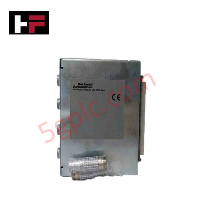
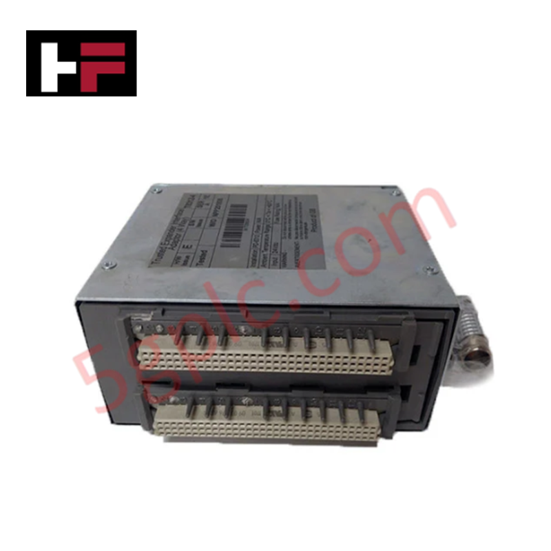
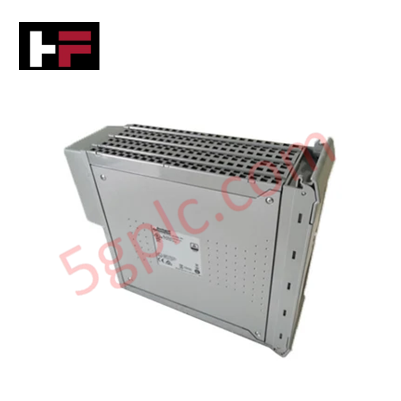
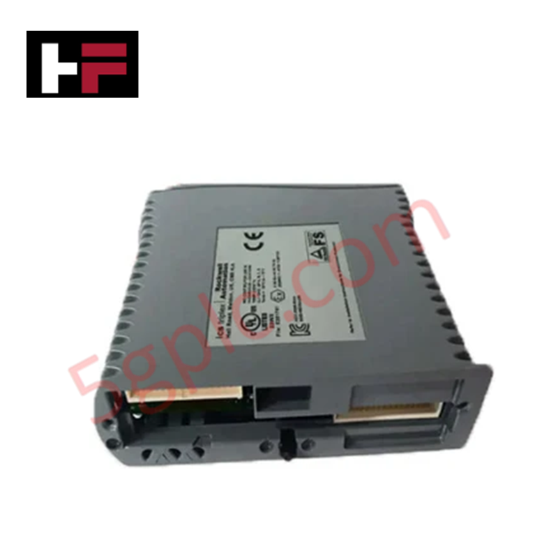
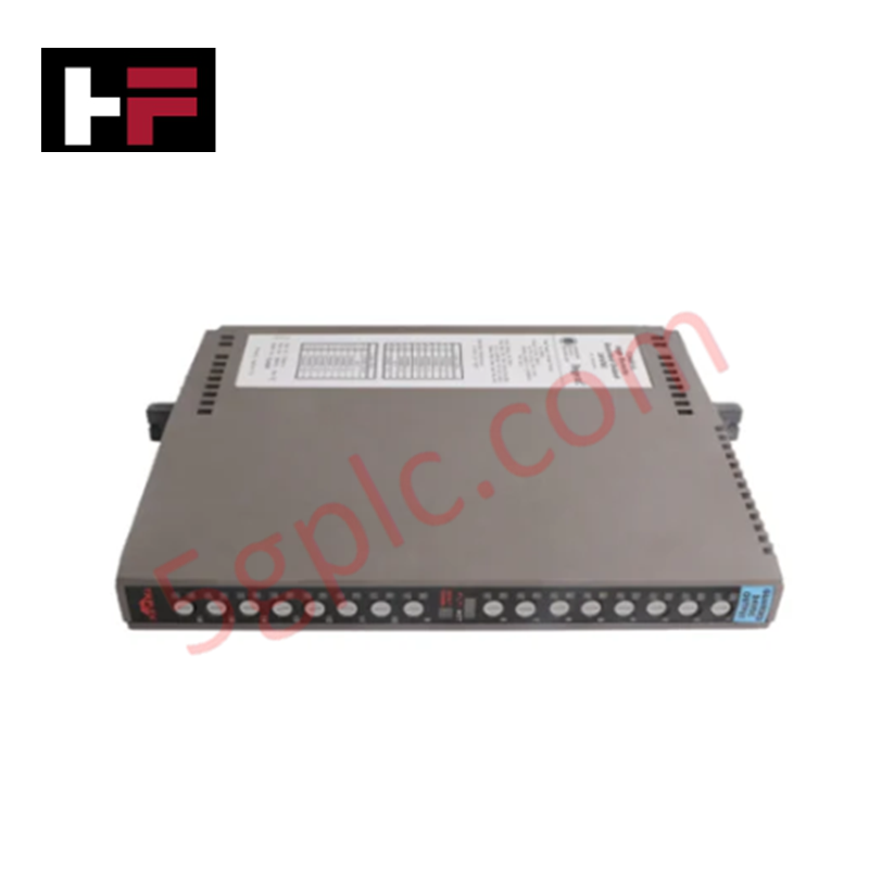
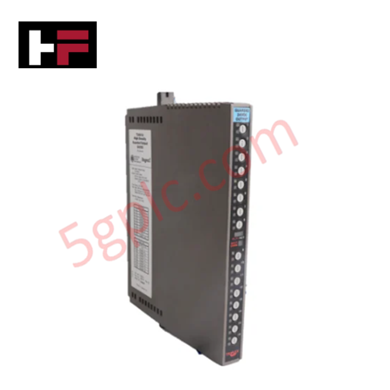
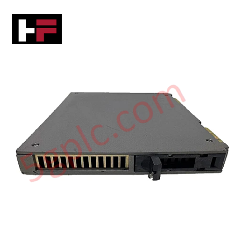
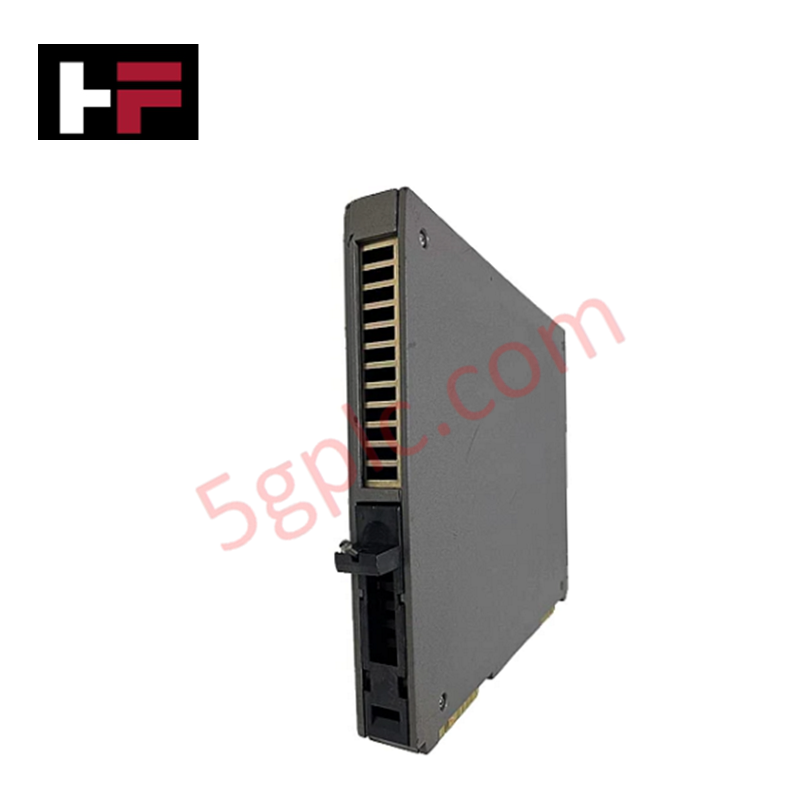
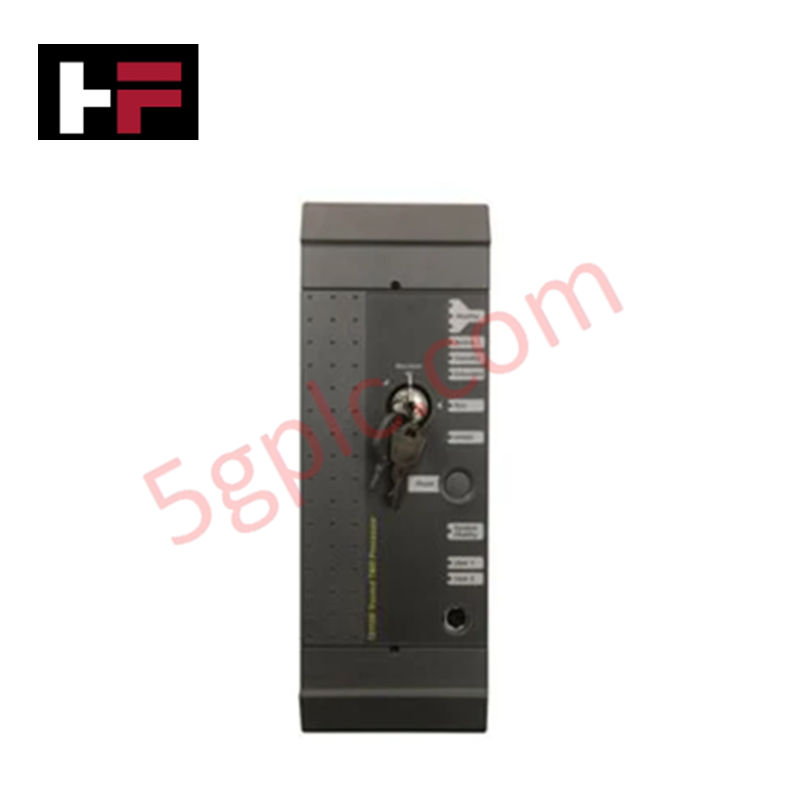
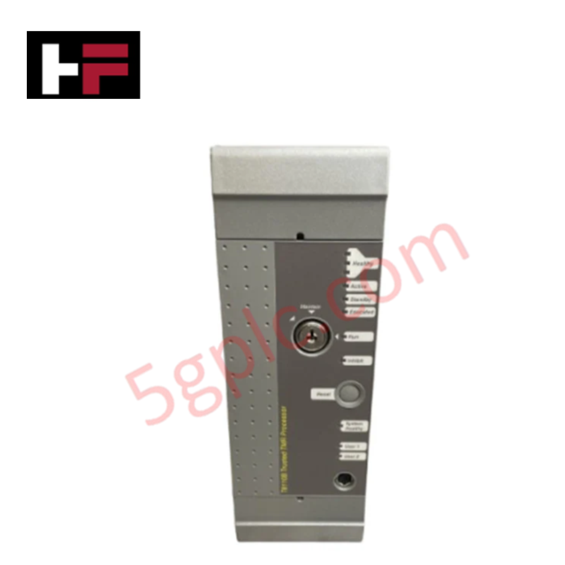
Configured for high-density I/O expansion in Trusted TMR control networks, the ICS Triplex T8312 (T8312 Expander Interface Adapter) provides direct physical and electrical execution. The module serves as a bridge between the controller chassis and remote expander chassis, managing the deterministic data link required for modular system scaling.
Suffix Breakdown & Model Matrix
| Model | Description |
|---|---|
| T8312/4 | Expander Interface Adapter, supports up to 4 chassis |
| T8312/7 | Expander Interface Adapter, supports up to 7 chassis |
Hardware Specifications
| Parameter | Specification |
|---|---|
| Model | T8312 |
| Brand | ICS Triplex |
| Weight | 0.65 kg |
| Operating Temp | Standard Industrial |
| Connectivity | Multi-chassis support (4 or 7 units) |
SIS Triple Modular Redundancy (TMR) Architecture
The T8312 integrates into the triple modular redundancy (TMR) 2oo3 architecture to ensure fail-safe state execution across expanded I/O segments. The module maintains synchronized communication paths, allowing the controller to perform voting on data received from remote chassis. Galvanic isolation is implemented at the bus interface level to prevent the propagation of backplane noise, ensuring that the physical link between the controller and the expander racks remains deterministic and immune to common-mode electrical disturbances.
Frequently Asked Questions
Q: How should the DIP switches be configured for multiple chassis expansion?
A: The controller chassis ID is set to #1. Expander chassis IDs are set via DIP switches from 2 to 8. For expansion beyond seven chassis, additional adapters must be configured with IDs 9 to 15, which are then mapped accordingly within the system software.
Q: Is the T8312 module hot-swappable while the system is operational?
A: The T8312 supports hot-swapping within the Trusted TMR backplane. Before removing or installing the module, ensure the system software is set to maintenance mode for the corresponding expander node to avoid triggering diagnostic fault logs or unintended system responses.
Field Installation Guidelines
- Ensure the chassis power is stable before seating the T8312 into the backplane connector.
- Configure the DIP switches for the correct chassis ID prior to module insertion to ensure proper addressing on the backplane bus.
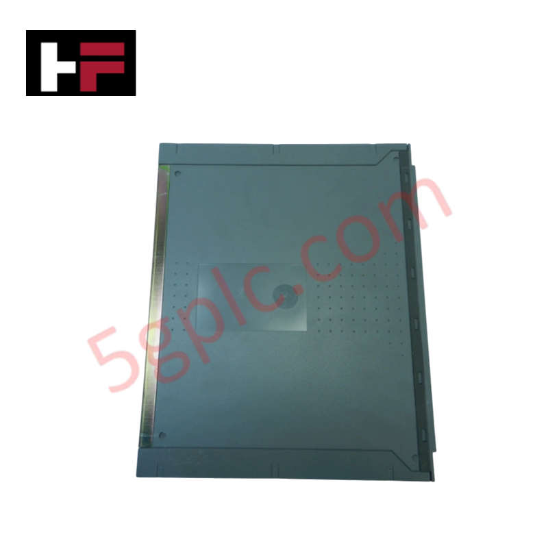
- Secure the module using the front-panel captive screws to establish a robust ground connection to the chassis.
- Verify the integrity of the interconnection cabling between the controller chassis and the expander racks to prevent communication jitter.
- Perform a configuration audit via the engineering workstation to confirm that the software registry matches the physical DIP switch settings for the assigned chassis IDs.
Additional Information
- 100% Genuine Parts: All products are original and authentic, ensuring reliable industrial performance.
- 30-Day Refund Guarantee: Return any in-stock item within 30 days in original, unopened packaging for a full refund (excluding shipping and fees).
- 12-Month Warranty: Covers defects in materials or workmanship; excludes misuse, normal wear, or unauthorized modifications.
- Worldwide Shipping: We ship via USPS, UPS, FedEx, and DHL. Delivery times vary by country and may be subject to customs or import fees.
- Support & Contact: Technical and warranty assistance is available anytime. Contact us here: Contact.
- Purchase Guidance: Check product specifications and compatibility carefully before ordering to ensure proper application.


Tech & Buying Guide

Why 24V DC Power Supplies Standardize Modern Industrial Automation
Industrial control cabinets worldwide rely on 24V DC as the universal power standard for field instrumentation, sensors, and controllers. Walk into any manufacturing plant, and you will find PLCs, human-machine interfaces (HMIs), and smart actuators running on extra-low voltage DC. Standardizing on 24V DC enhances operational safety, lowers cabinet footprint, and maintains steady control performance across factory networks.

Essential Motion Control Commands: A Practical Guide for Engineers
Automation engineers often rely on precise position and speed control to drive modern factory machinery. Modern industrial systems, such as Programmable Logic Controllers (PLCs) and Distributed Control Systems (DCS), depend heavily on standardized motion instructions. Mastering these commands ensures operational safety, protects mechanical components, and optimizes cycle times across production lines.

Mastering Modern Industrial Joystick Controls in Heavy Automation
Industrial joysticks play a pivotal role in human-machine interaction across heavy material handling and mobile hydraulics. These tactile controllers translate complex operator movements into precise electrical signals for PLCs, motion controllers, and DCS networks. Consequently, selecting and installing the right joystick architecture ensures operator safety, reduces fatigue, and optimizes equipment performance.