


Product Details
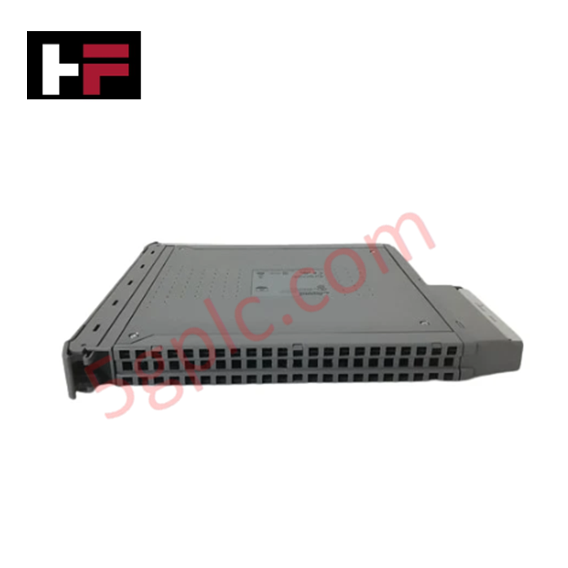
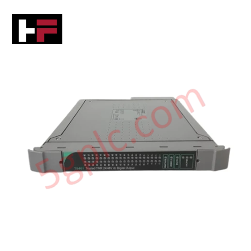
Configured for high-density signal acquisition within the Trusted TMR system, the ICS TRIPLEX T8800 (T8800 Digital Input Module) provides direct physical and electrical execution. The module processes up to 40 individual 24 VDC digital input signals, converting field-level binary states into deterministic data packets for integration into the control logic execution path.
Hardware Specifications
| Parameter | Specification |
|---|---|
| Model | T8800 |
| Brand | ICS TRIPLEX |
| Operating Temp | Standard Industrial |
| Input Capacity | 40 Channels |
| Input Voltage | 24 VDC |
SIS Triple Modular Redundancy (TMR) Architecture
The T8800 operates within a triple modular redundancy (TMR) 2oo3 architecture, where input states are sampled across three independent processing channels. Internal voting logic compares these inputs in real-time to identify and isolate discrepancies caused by hardware faults. This architecture facilitates fail-safe state execution, ensuring that a single-point failure within the input signal path does not cause an erroneous transition in the safety-critical control logic. Galvanic isolation is maintained between the field-side inputs and the system backplane to prevent transient signal propagation.
Frequently Asked Questions
Q: Does the T8800 support online hot-swapping?
A: Yes, the T8800 is designed for hot-swap capability within a powered Trusted TMR backplane. Ensure that the associated system software is configured to handle the temporary loss of input data during the module removal and insertion process to avoid spurious safety shutdowns.
Q: How should unused input channels be terminated on the T8800?
A: Unused channels should be left disconnected or terminated according to the specific application logic configuration to prevent floating inputs. Confirm that input filtering parameters in the software configuration are adjusted to match the impedance characteristics of the connected field devices.
Field Installation Guidelines
- Ensure the TMR rack power is stabilized at the nominal 24 VDC level before module insertion.
- Align the module with the designated backplane slot and engage the locking mechanism to ensure positive contact with the bus connector.
- Terminate field devices to the corresponding termination assembly, ensuring that common return paths are connected to the system reference ground to minimize noise.
- Verify that field wiring is properly shielded, with shields terminated at the enclosure ground point to suppress electromagnetic interference.
- Perform a loop check for each of the 40 channels post-installation to verify the correspondence between field device state transitions and the input data mapped in the control processor.
Additional Information
- 100% Genuine Parts: All products are original and authentic, ensuring reliable industrial performance.
- 30-Day Refund Guarantee: Return any in-stock item within 30 days in original, unopened packaging for a full refund (excluding shipping and fees).
- 12-Month Warranty: Covers defects in materials or workmanship; excludes misuse, normal wear, or unauthorized modifications.
- Worldwide Shipping: We ship via USPS, UPS, FedEx, and DHL. Delivery times vary by country and may be subject to customs or import fees.
- Support & Contact: Technical and warranty assistance is available anytime. Contact us here: Contact.
- Purchase Guidance: Check product specifications and compatibility carefully before ordering to ensure proper application.


Tech & Buying Guide

Why 24V DC Power Supplies Standardize Modern Industrial Automation
Industrial control cabinets worldwide rely on 24V DC as the universal power standard for field instrumentation, sensors, and controllers. Walk into any manufacturing plant, and you will find PLCs, human-machine interfaces (HMIs), and smart actuators running on extra-low voltage DC. Standardizing on 24V DC enhances operational safety, lowers cabinet footprint, and maintains steady control performance across factory networks.

Essential Motion Control Commands: A Practical Guide for Engineers
Automation engineers often rely on precise position and speed control to drive modern factory machinery. Modern industrial systems, such as Programmable Logic Controllers (PLCs) and Distributed Control Systems (DCS), depend heavily on standardized motion instructions. Mastering these commands ensures operational safety, protects mechanical components, and optimizes cycle times across production lines.

Mastering Modern Industrial Joystick Controls in Heavy Automation
Industrial joysticks play a pivotal role in human-machine interaction across heavy material handling and mobile hydraulics. These tactile controllers translate complex operator movements into precise electrical signals for PLCs, motion controllers, and DCS networks. Consequently, selecting and installing the right joystick architecture ensures operator safety, reduces fatigue, and optimizes equipment performance.