


Product Details
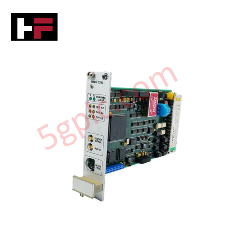
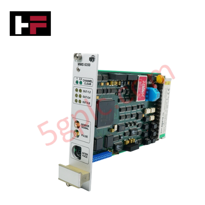
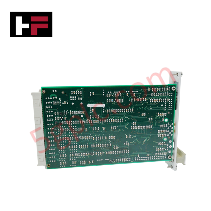
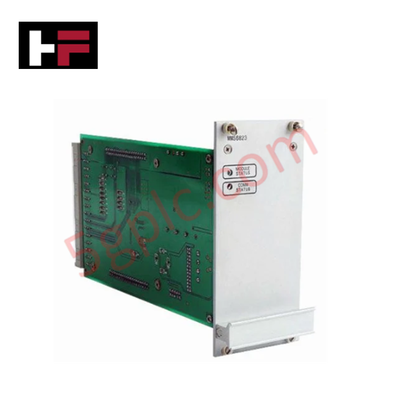
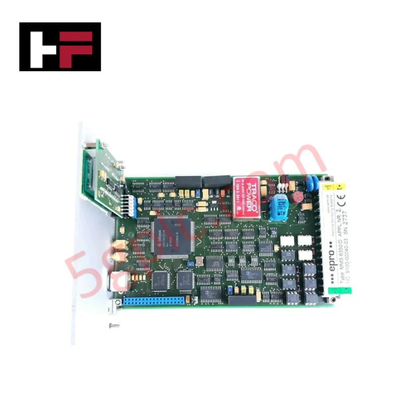
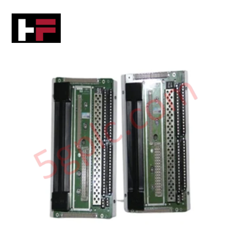
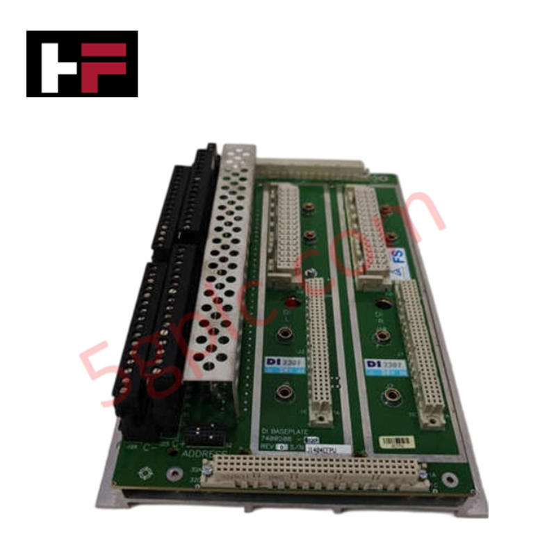
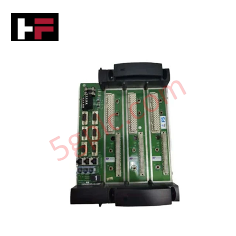
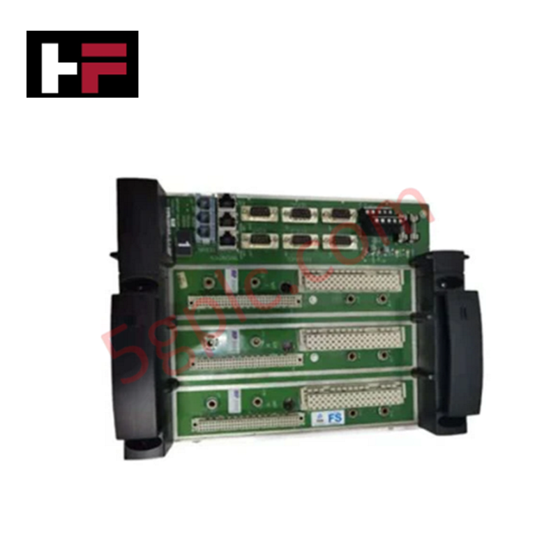
Configured for high-speed pulse acquisition and overspeed detection in TSI (Turbine Supervisory Instrumentation) platforms, the Emerson EPRO MMS 6350D (MMS 6350D Digital Overspeed Protection System) provides direct electrical execution of turbine speed monitoring and protection logic.
Hardware Specifications
| Parameter | Specification |
|---|---|
| Model | MMS 6350D |
| Brand | Emerson EPRO |
| Operating Temp | Standard industrial range |
| Power Consumption | Not specified |
| Frequency Range | 0 to 16 kHz (-3 dB) |
| Input Resistance | 100 kOhm |
| TTL Output Range | 0 to 5 V |
Mechanical Monitoring and TSI Characteristics
The MMS 6350D is designed to process differential sensor inputs for turbine rotor dynamics analysis. To ensure accurate overspeed protection, it is necessary to verify proper signal scaling and maintain consistent rotor target clearance to avoid signal clipping or loss. The device provides buffered SMB outputs and TTL pulses for downstream monitoring systems. When installing these sensors, cross-talk suppression must be maintained by ensuring that signal cabling is shielded and routed independently from high-current actuator control lines. The frequency acquisition path is protected against both open-circuit and short-circuit faults to ensure the protection system remains active during field sensor failures.
Frequently Asked Questions
Q: Can the TTL output be used to drive multiple monitoring devices simultaneously?
A: The TTL output is designed with a permissible load of >= 1 kOhm. Loading the output beyond this limit may degrade the pulse signal edge quality and trigger transition errors in the connected protective logic.
Q: How is the input frequency range and accuracy affected by cable length?
A: The 100 kOhm input resistance is sensitive to capacitive loading. To maintain the specified accuracy (±1% of f.s.d.) and frequency bandwidth (0 to 16 kHz), use low-capacitance shielded cabling and minimize the total distance between the sensor and the MMS 6350D input.
Field Installation Guidelines
- Ensure the differential input signal polarity matches the system requirements to avoid signal inversion at the overspeed detection stage.
- Terminate the signal cable shields at the designated common ground point to prevent ground loops that could introduce noise into the pulse acquisition path.
- Use SMB connectors for the front-facing buffered outputs to ensure a secure, low-impedance connection during testing and calibration.
- Separate the 0-5 V TTL output cabling from power-carrying conductors to prevent electromagnetic coupling from triggering false speed readings.
- Verify that the sensor-to-target gap is calibrated to provide the required signal voltage amplitude (0 to 27.3 VDC input range) prior to final system activation.
Additional Information
- 100% Genuine Parts: All products are original and authentic, ensuring reliable industrial performance.
- 30-Day Refund Guarantee: Return any in-stock item within 30 days in original, unopened packaging for a full refund (excluding shipping and fees).
- 12-Month Warranty: Covers defects in materials or workmanship; excludes misuse, normal wear, or unauthorized modifications.
- Worldwide Shipping: We ship via USPS, UPS, FedEx, and DHL. Delivery times vary by country and may be subject to customs or import fees.
- Support & Contact: Technical and warranty assistance is available anytime. Contact us here: Contact.
- Purchase Guidance: Check product specifications and compatibility carefully before ordering to ensure proper application.

Tech & Buying Guide

Essential SCADA Features for Modern IoT-Enabled Industrial Automation
The convergence of traditional SCADA systems with the Industrial Internet of Things (IIoT) has redefined factory automation. Choosing a robust platform requires more than just standard monitoring capabilities. In this era of Industry 4.0, your supervisory system must bridge the gap between legacy control systems and enterprise-level data integration.

Selecting Rockwell Automation Allen-Bradley PLCs for Small and Mid-Sized Applications
Rockwell Automation remains a cornerstone in global industrial automation. Their Allen-Bradley brand provides a comprehensive portfolio of control systems designed to meet diverse production requirements. Choosing the right programmable logic controller (PLC) is critical for system reliability and scalability. This guide analyzes the Micro and Compact Logix families to help you select the optimal solution for small and medium-scale projects.

Strategic Selection: Choosing the Right SCADA Software for Your PLC Project
In industrial automation, the SCADA (Supervisory Control and Data Acquisition) system acts as the bridge between raw machine data and actionable human intelligence. Selecting the incorrect software platform can lead to integration bottlenecks, scalability issues, and excessive long-term maintenance costs. As an automation consultant with 15 years of experience, I have guided many projects through the selection process. Below are the essential criteria for choosing a platform that ensures both performance and longevity.