










Product Details
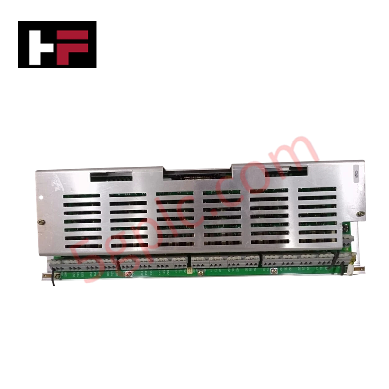
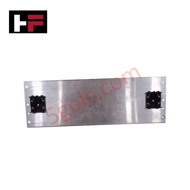
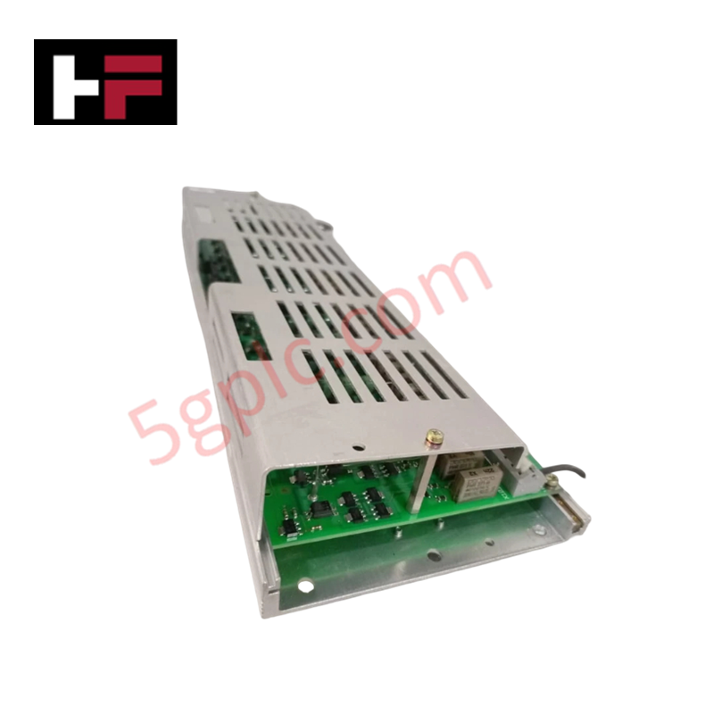
Configured for discrete state acquisition and contact monitoring in system subracks, the ABB UF C092 BE01 HIEE300910R0001 (UF C092 BE01 Binary Input Module) provides direct physical/electrical execution across ABB control platforms. The module interfaces external dry contacts, limit switches, and binary sensors with the central processing unit via the subrack backplane logic bus.
Hardware Specifications
| Parameter | Specification |
|---|---|
| Model | UF C092 BE01 HIEE300910R0001 |
| Brand | ABB |
| Origin | Switzerland |
| Weight | 1.0 kg net (Gross: 1.1 kg) |
| Dimensions | 38.0 cm x 6.0 cm x 13.0 cm (14.96 in x 2.36 in x 5.12 in) |
| Operating Temp | 0 to +60 deg C (Storage: -40 to +70 deg C) |
| Power Consumption | Logic side powered via subrack backplane bus |
| Module Type | Binary / Digital Input Module |
| Tariff Code | 85371092 |
| Mounting Format | Dedicated subrack slot insertion |
Backplane Bus Communication Velocity and Firmware Flash Compatibility
The UF C092 BE01 module connects into the subrack backplane, ensuring high backplane bus communication velocity during real-time scan cycles. Onboard non-volatile memory provides firmware flash compatibility, maintaining persistent channel configuration data and allowing field system updates without board removal. Built-in input filtering circuit logic reduces signal chatter and debounce noise from field contact switches before transferring binary state vectors to the controller backplane.
Frequently Asked Questions
Q: Does the UF C092 BE01 binary input module support live insertion during system operation?
A: No. Power to the subrack backplane and field input supply circuits must be disconnected prior to inserting or removing the board to prevent contact arcing and logic bus disruptions.
Q: How does the module handle high field contact chatter and electrical bounce?
A: Internal hardware RC filtering and digital debounce circuit timing process incoming binary signal transitions, suppressing false status triggers before data is sent across the backplane bus.
Q: What is the primary function of the front panel retention mechanics?
A: Captive front panel screws secure the module physically into the subrack chassis frame, maintaining continuous backplane multi-pin connector contact and establishing proper chassis grounding path.
Field Installation Guidelines
- De-energize all primary rack backplane power sources and isolate external voltage lines feeding the binary input terminal blocks prior to installation.
- Align the top and bottom edges of the module circuit board with the subrack guide rails.
- Slide the unit firmly into the slot until the rear multi-pin edge connector seats completely into the backplane socket.
- Fasten top and bottom retaining screws to 0.4 Nm to prevent connector loosening due to mechanical vibration.
- Connect input wiring using twisted-pair cables, bonding all external wire shielding to the enclosure ground rail to prevent electromagnetic interference.
Additional Information
- 100% Genuine Parts: All products are original and authentic, ensuring reliable industrial performance.
- 30-Day Refund Guarantee: Return any in-stock item within 30 days in original, unopened packaging for a full refund (excluding shipping and fees).
- 12-Month Warranty: Covers defects in materials or workmanship; excludes misuse, normal wear, or unauthorized modifications.
- Worldwide Shipping: We ship via USPS, UPS, FedEx, and DHL. Delivery times vary by country and may be subject to customs or import fees.
- Support & Contact: Technical and warranty assistance is available anytime. Contact us here: Contact.
- Purchase Guidance: Check product specifications and compatibility carefully before ordering to ensure proper application.




Tech & Buying Guide

Understanding Marshalling Cabinets in Industrial Control Systems Architecture
Industrial control system deployments rely on structured signal distribution to bridge field instrumentation with central processing hardware. A marshalling cabinet serves as the vital intermediate connection point between heavy field home-run multi-pair cables and delicate input/output (I/O) modules housed inside Programmable Logic Controller (PLC) or Distributed Control System (DCS) enclosures. By segregating field cable terminations from control hardware, engineers maintain system flexibility, safeguard controller components, and streamline commissioning workflows.

FAT vs SAT in Industrial Control Systems: Key Differences and Execution Guide
Industrial control system deployment relies on strict verification protocols to guarantee operational safety, system stability, and regulatory compliance. Commissioning complex Programmable Logic Controller (PLC) racks, Distributed Control Systems (DCS), and Safety Instrumented Systems (SIS) requires two critical milestones: the Factory Acceptance Test (FAT) and the Site Acceptance Test (SAT). Both procedures validate that system automation meets design specifications, but they occur at different stages of project execution and target distinct operational risks.

Hub vs Switch vs Router in Industrial Automation Architecture
Modern factory automation relies on reliable industrial networking infrastructure to exchange real-time field data across operational technology systems. Engineers often encounter networking hardware like hubs, switches, and routers when integrating Programmable Logic Controllers, Distributed Control Systems, and SCADA monitoring nodes. Although these devices share physical ports, they operate at different layers of the Open Systems Interconnection reference model and deliver distinct traffic management capabilities.