


Product Details
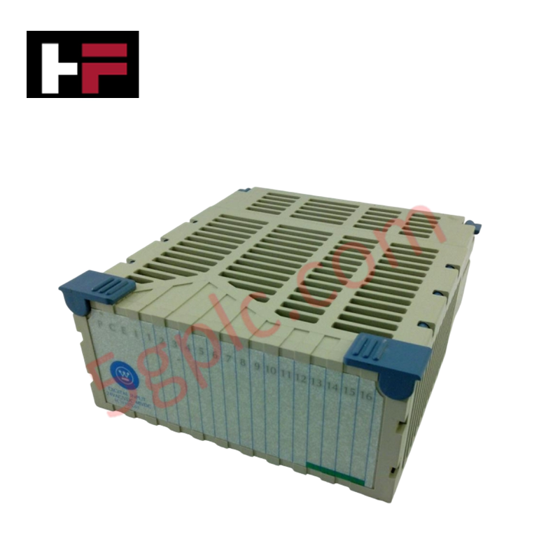
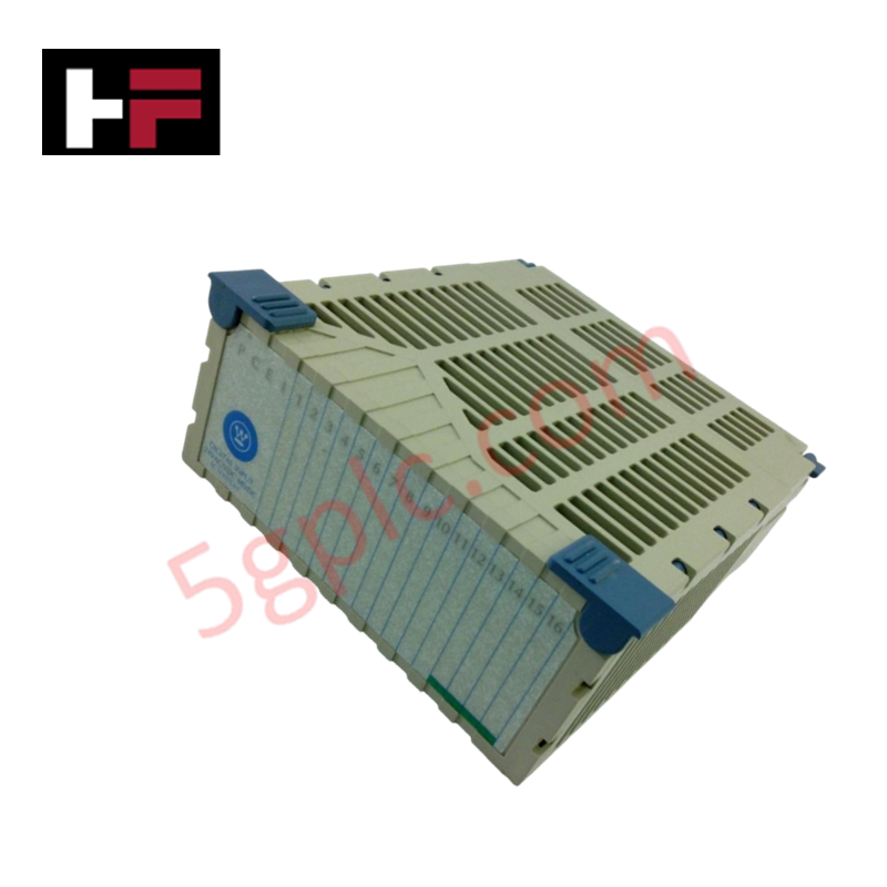
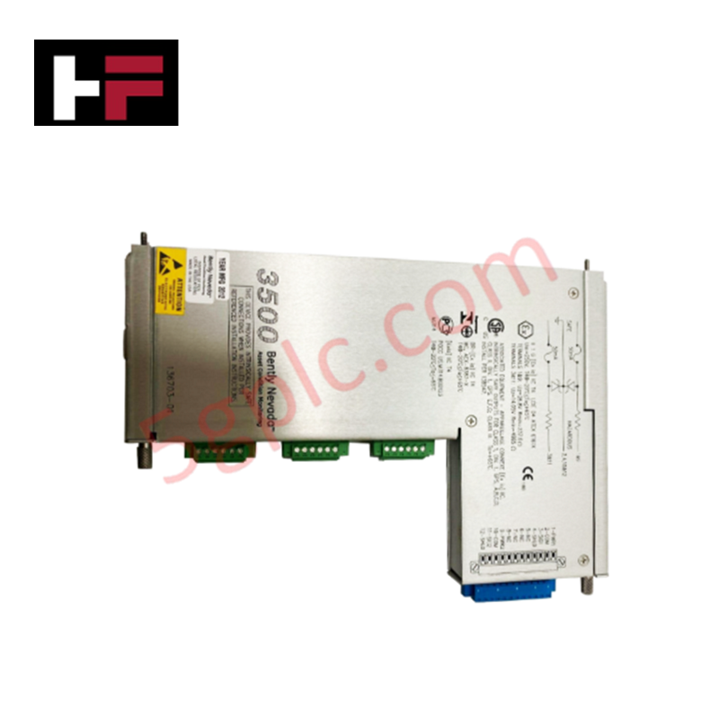
The Westinghouse Emerson 1C31161G02, also cataloged as the 1C31161G02 Analog Input Module, operates as a dedicated hardware component for processing Resistance Temperature Detector (RTD) signals within Ovation control system platforms. This module provides direct physical electrical execution for converting analog resistance values from field sensors into digital data for process monitoring and control loop logic.
Hardware Specifications
| Parameter | Specification |
|---|---|
| Model | 1C31161G02 |
| Brand | Westinghouse Emerson |
| Weight | 0.70 lbs |
| Input Type | Analog RTD |
Process Control Connectivity and Signal Isolation
The 1C31161G02 architecture supports channel-to-channel isolation to maintain the precision of thermal measurements in industrial environments. This galvanic separation is necessary to suppress common-mode noise and prevent ground loops that interfere with RTD resistance sensing. The module is fully compatible with 4-20 mA HART loop protocol diagnostics when deployed in integrated field architectures, allowing for the transmission of sensor status and diagnostic data back to the central controller to ensure measurement integrity.
Frequently Asked Questions (FAQ)
Q: Does the 1C31161G02 support hot-swapping functionality during system operation?
A: The module supports hot-swap operations within the designated I/O rack. Ensure the control system is placed in a maintenance mode for the corresponding channel before module extraction to prevent fault propagation.
Q: Is this module compatible with standard 3-wire RTD configurations?
A: The input circuitry is designed for standard RTD input types. Refer to the specific wiring terminal block diagram to verify correct lead-wire compensation and termination requirements.
Field Installation Guidelines
- Inspect the backplane interface for pin integrity and cleanliness before module insertion.
- Align the module with the chassis guide rails and apply steady pressure to engage the backplane connector.
- Secure the module via the integrated locking tabs to prevent displacement from vibration.
- Terminate field wiring at the terminal block, ensuring that shielded, twisted-pair cables are used to minimize electromagnetic interference (EMI).
- Bond all cable shields to a single-point ground bus within the cabinet to maintain low-impedance paths for common-mode noise discharge.
Additional Information
- 100% Genuine Parts: All products are original and authentic, ensuring reliable industrial performance.
- 30-Day Refund Guarantee: Return any in-stock item within 30 days in original, unopened packaging for a full refund (excluding shipping and fees).
- 12-Month Warranty: Covers defects in materials or workmanship; excludes misuse, normal wear, or unauthorized modifications.
- Worldwide Shipping: We ship via USPS, UPS, FedEx, and DHL. Delivery times vary by country and may be subject to customs or import fees.
- Support & Contact: Technical and warranty assistance is available anytime. Contact us here: Contact.
- Purchase Guidance: Check product specifications and compatibility carefully before ordering to ensure proper application.


Tech & Buying Guide

Why 24V DC Power Supplies Standardize Modern Industrial Automation
Industrial control cabinets worldwide rely on 24V DC as the universal power standard for field instrumentation, sensors, and controllers. Walk into any manufacturing plant, and you will find PLCs, human-machine interfaces (HMIs), and smart actuators running on extra-low voltage DC. Standardizing on 24V DC enhances operational safety, lowers cabinet footprint, and maintains steady control performance across factory networks.

Essential Motion Control Commands: A Practical Guide for Engineers
Automation engineers often rely on precise position and speed control to drive modern factory machinery. Modern industrial systems, such as Programmable Logic Controllers (PLCs) and Distributed Control Systems (DCS), depend heavily on standardized motion instructions. Mastering these commands ensures operational safety, protects mechanical components, and optimizes cycle times across production lines.

Mastering Modern Industrial Joystick Controls in Heavy Automation
Industrial joysticks play a pivotal role in human-machine interaction across heavy material handling and mobile hydraulics. These tactile controllers translate complex operator movements into precise electrical signals for PLCs, motion controllers, and DCS networks. Consequently, selecting and installing the right joystick architecture ensures operator safety, reduces fatigue, and optimizes equipment performance.