














Product Details
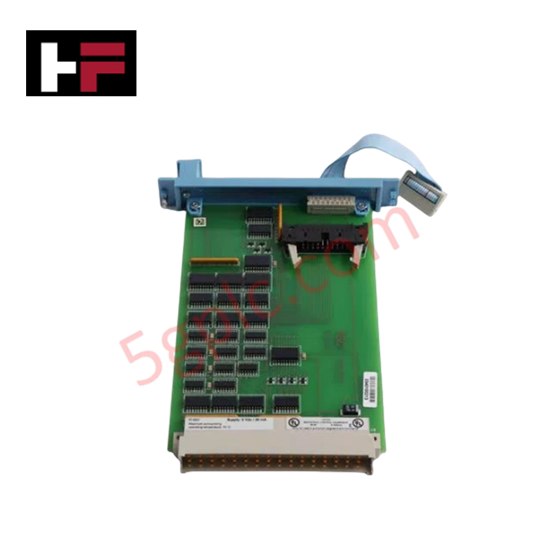
The Honeywell FC-IO-0002 V1.1, also cataloged as the FC-IO-0002 I/O Extender Module, operates as a dedicated hardware component for localized chassis signal extension and backplane bus expansion within Honeywell Safety Manager platforms.
Hardware Specifications
| Parameter | Specification |
|---|---|
| Model | FC-IO-0002 V1.1 |
| Brand | Honeywell |
| Origin | USA |
| Weight | 0.24 kg |
| Dimensions | 17.8 cm x 4.6 cm x 24.9 cm |
| Operating Temp | -20 to +60 deg C |
| Power Consumption | Standard backplane bus draw |
Process Control & DCS Signal Processing Characteristics
The FC-IO-0002 V1.1 module utilizes high-density channel-to-channel isolation architecture to prevent ground loops across field-side signals. Integrated line filtering suppresses high-frequency electromagnetic noise before passing digital logic and process variables to primary controller racks. Onboard interface conditioning circuits ensure precision processing for standard 4-20 mA HART loop protocol signals and remote field termination unit connectivity.
Frequently Asked Questions
Q: Does the FC-IO-0002 V1.1 support hot-swapping during live rack execution?
A: Hot-swapping is permitted provided the carrier chassis retains backplane voltage stability and standard ESD precautions are implemented during physical extraction.
Q: How are cable shield terminations managed on the FC-IO-0002 V1.1 assembly?
A: Field cabling shields must connect directly to the main cabinet earth bar to prevent external transient injection into internal logic circuits.
Q: What mounting orientations are supported for thermal compliance?
A: The module must be inserted vertically in standard chassis slots to maintain natural convective airflow across internal circuit board components.
Field Installation Guidelines
- Mechanical Mounting: Align the module card edges with the designated rack guides. Slide the unit until the rear connectors click into the backplane, then hand-tighten the front locking screws.
- Grounding & Shielding: Connect signal cable shields to the local enclosure ground bus bar using low-impedance grounding clamps. Keep field communication lines separated from high-voltage AC lines by at least 30 cm.
- Power Verification: Confirm backplane supply rails are within specification prior to energizing the module.
- Thermal Clearance: Maintain a minimum 50 mm vertical clearance above and below the card chassis to facilitate heat dissipation inside the control cabinet.
Additional Information
- 100% Genuine Parts: All products are original and authentic, ensuring reliable industrial performance.
- 30-Day Refund Guarantee: Return any in-stock item within 30 days in original, unopened packaging for a full refund (excluding shipping and fees).
- 12-Month Warranty: Covers defects in materials or workmanship; excludes misuse, normal wear, or unauthorized modifications.
- Worldwide Shipping: We ship via USPS, UPS, FedEx, and DHL. Delivery times vary by country and may be subject to customs or import fees.
- Support & Contact: Technical and warranty assistance is available anytime. Contact us here: Contact.
- Purchase Guidance: Check product specifications and compatibility carefully before ordering to ensure proper application.


Tech & Buying Guide

Marshalling Cabinet Preventive Maintenance: Essential Healthiness Checks for PLC, DCS, and ESD Systems
Marshalling cabinets serve as the vital interface between field instrumentation and control room electronics in modern process facilities. Regular preventive maintenance of these cabinets ensures signal integrity across programmable logic controllers (PLCs), distributed control systems (DCS), and emergency shutdown (ESD) networks. System technicians must execute structured inspection protocols to mitigate environmental risks, identify loose wiring, and maintain continuous operational readiness.

Spatial Computing in Industrial Automation: Elevating PLC and DCS Operations with AR and VR
Industry 4.0 integrates digital intelligence into field operations, transforming factory automation landscapes worldwide. Spatial technologies—specifically Augmented Reality (AR) and Virtual Reality (VR)—redefine how engineers interact with industrial control systems. By bridging computer-generated CAD models with real-time operational technology (OT) data, immersive displays enable intuitive monitoring, rapid diagnostics, and safer maintenance across complex processing facilities.

Master Acceptance Testing: Understanding FAT and SAT in Industrial Control Systems
Factory Acceptance Testing (FAT) and Site Acceptance Testing (SAT) serve as critical quality assurance gateways in complex industrial control systems. Both procedures verify that programmable logic controllers (PLCs), distributed control systems (DCS), and associated field devices meet strict functional specifications. However, executing these tests effectively requires clear delineation between off-site staging and final field commissioning.