


Product Details
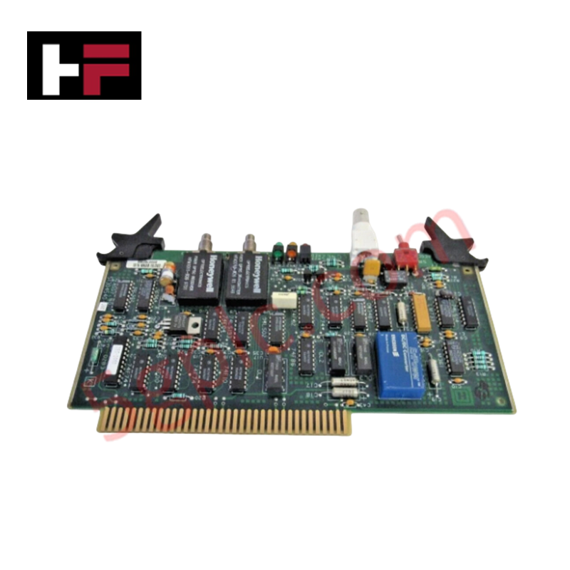
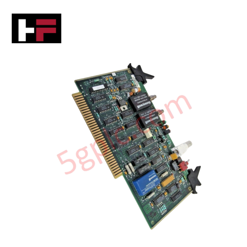
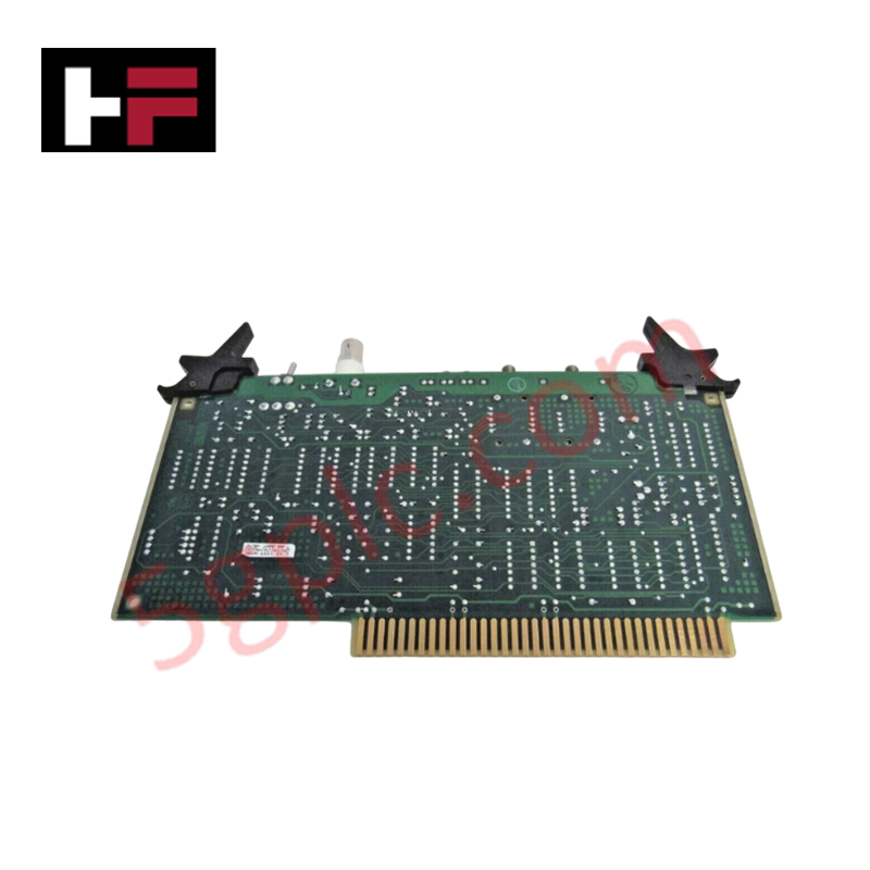
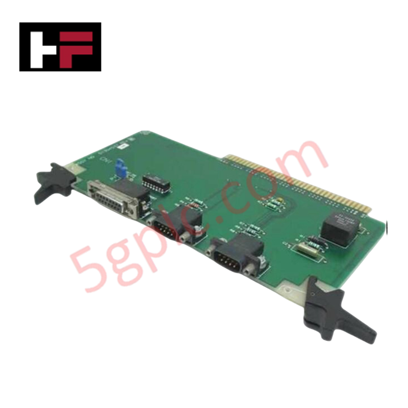
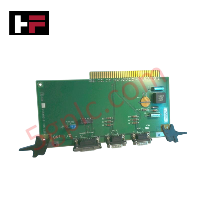
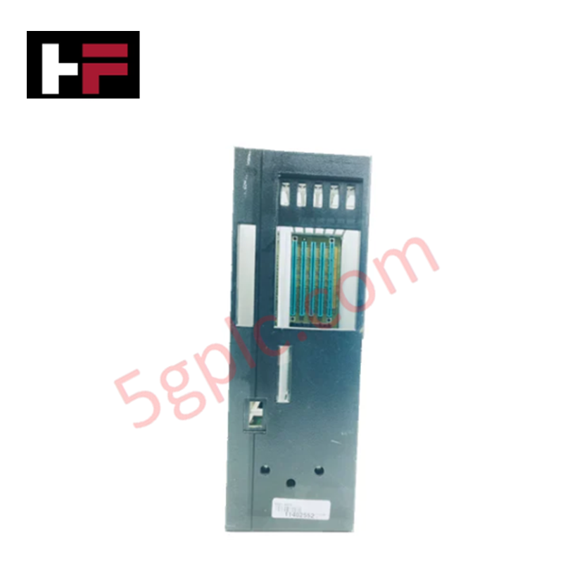
Configured for Local Control Network (LCN) extension in TDC 3000 distributed control system architectures, the Honeywell 51304540-100 (51304540-100) LCNE2 paddle board provides direct physical/electrical execution of fiber optic signal conversion. This hardware component serves as a dedicated interface for extending the LCN backbone, facilitating high-speed data transmission between control processors and remote field nodes.
Hardware Specifications
| Parameter | Specification |
|---|---|
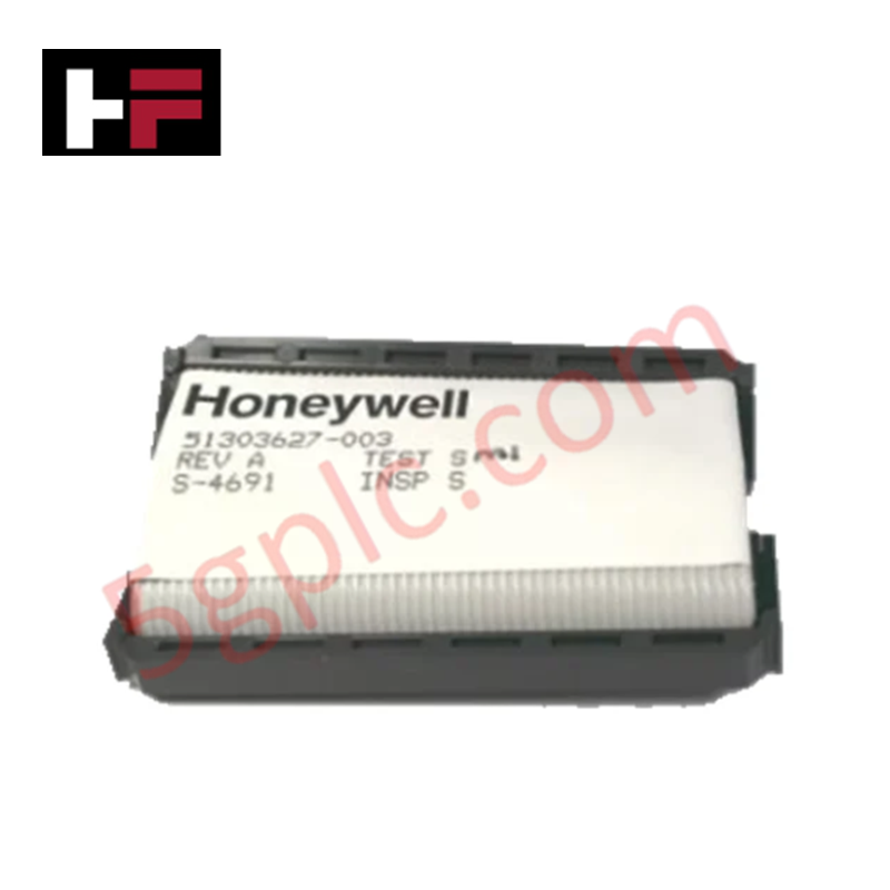
| Model | 51304540-100 |
| Brand | Honeywell |
| Dimensions | Standard paddle board form factor |
| Operating Temp | Consult system technical manual |
| Power Consumption | Dependent on host I/O rack |
| Performance | 20 MHz processing speed; 16 input/16 output channels |
Cold Junction Compensation (CJC) and Channel-to-Channel Isolation
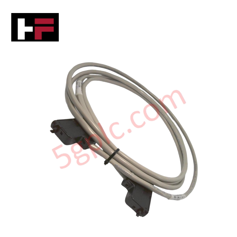
The 51304540-100 LCNE2 paddle board incorporates high-density I/O management within the TDC 3000 environment. To maintain signal integrity across its 16 input and 16 output channels, the board utilizes channel-to-channel isolation to prevent potential propagation of electrical faults. In configurations where these channels interface with analog sensor loops, the board supports the necessary precision required for downstream processing, such as cold junction compensation (CJC) for temperature sensing elements. The integration of SMA fiber optic connectors further ensures electromagnetic immunity for long-distance data transmission, preserving the deterministic nature of the control network.
Frequently Asked Questions
Q: Does the 51304540-100 support hot-swapping within the I/O rack?
A: Hot-swapping capabilities are strictly defined by the host I/O rack backplane and the local controller firmware version. Verify that the system is configured for live module replacement before performing any maintenance to avoid CPU communication interrupts.
Q: Is the 16 KB EEPROM user-programmable?
A: The EEPROM is utilized primarily for board-level configuration and diagnostic data storage required by the LCN interface protocols. Modification of this memory by the user is not supported and may result in the loss of module-specific calibration data.
Field Installation Guidelines
- Fiber Optic Handling: Inspect SMA fiber optic connectors for contamination prior to mating. Clean the ferrule ends with approved optical grade solvent and lint-free wipes to prevent signal attenuation caused by dust or oils.
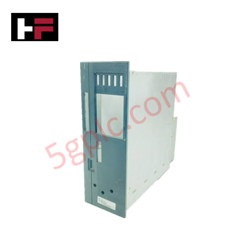
- Mechanical Insertion: Align the paddle board with the rack guide rails before engaging the backplane connector. Ensure the module is pushed firmly until the locking mechanism is secured, preventing intermittent connection due to mechanical vibration.
- Shielding and Grounding: Ensure the I/O rack chassis is properly bonded to the system protective earth (PE) ground. This is mandatory to maintain the electrical isolation characteristics of the paddle board circuitry.
- Cable Routing: Route fiber optic cabling with strict adherence to minimum bend radius specifications. Sharp bends will induce signal loss and potential micro-fractures in the fiber core, leading to network communication failures.
Additional Information
- 100% Genuine Parts: All products are original and authentic, ensuring reliable industrial performance.
- 30-Day Refund Guarantee: Return any in-stock item within 30 days in original, unopened packaging for a full refund (excluding shipping and fees).
- 12-Month Warranty: Covers defects in materials or workmanship; excludes misuse, normal wear, or unauthorized modifications.
- Worldwide Shipping: We ship via USPS, UPS, FedEx, and DHL. Delivery times vary by country and may be subject to customs or import fees.
- Support & Contact: Technical and warranty assistance is available anytime. Contact us here: Contact.
- Purchase Guidance: Check product specifications and compatibility carefully before ordering to ensure proper application.


Tech & Buying Guide

Implementing FIFO and LIFO Data Sequencing in PLC Programming
Data management serves as a cornerstone of modern industrial automation. Whether tracking materials on a conveyor or managing batch sequences in a process, engineers frequently rely on sequential logic. Two primary structures—First-In-First-Out (FIFO) and Last-In-First-Out (LIFO)—form the bedrock of this data handling. Mastering these blocks allows programmers to optimize complex machine operations efficiently.

Evolving SCADA System Architectures in Industrial Automation
A robust Supervisory Control and Data Acquisition (SCADA) system serves as the heartbeat of modern industrial operations. Understanding SCADA system architecture is vital for engineers designing efficient control systems. These architectures have evolved from isolated, monolithic structures to highly interconnected, networked ecosystems. Choosing the right design requires balancing data visibility, processing power, and long-term scalability requirements.
Choosing the Right Controller: PLC vs. Motion Controller in Industrial Automation
Selecting the optimal control architecture is a foundational decision in industrial automation. Engineers must frequently choose between a Programmable Logic Controller (PLC) and a dedicated Motion Controller. While both systems manage machinery, their underlying design philosophies differ significantly, impacting performance, scalability, and system integration.