


Product Details
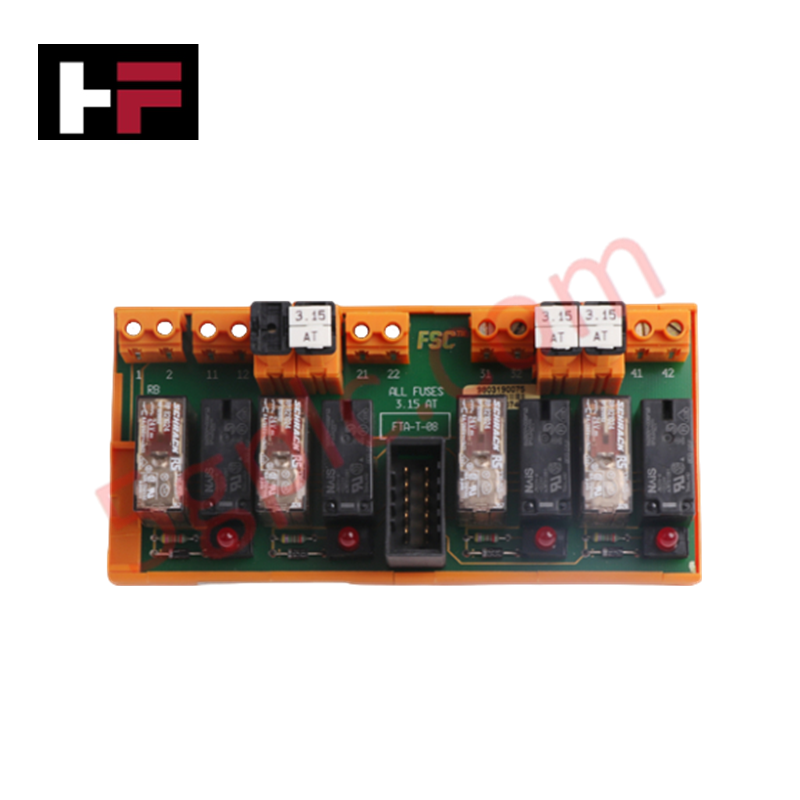
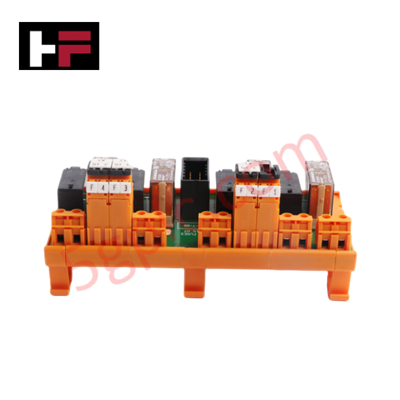
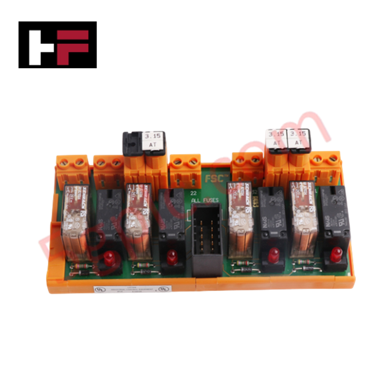
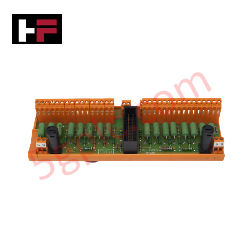
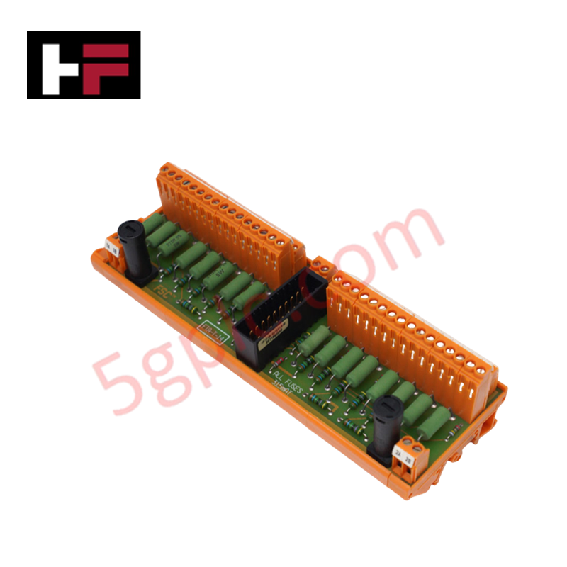
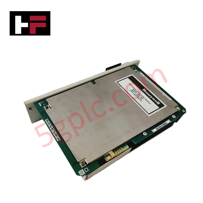
Configured for safety-critical digital switching in industrial control platforms, the Honeywell FTA-T-08 (FTA-T-08) Field Termination Assembly provides direct physical execution of 4-channel relay-based outputs. The assembly operates with a nominal input voltage of 24 V DC, facilitating secure load switching through fused, high-capacity relay contacts designed for demanding signal processing environments.
Hardware Specifications
| Parameter | Specification |
|---|---|
| Model | FTA-T-08 |
| Brand | Honeywell |
| Dimensions | Standard FTA rack format |
| Operating Temp | Consult system technical manual |
| Power Consumption | ~50 mA at 24 V |
| Output Channels | 4 channels |
| Switched Voltage | 250 V AC / 150 V DC |
Fail-safe State Execution
The FTA-T-08 assembly is engineered to facilitate fail-safe state execution, ensuring that in the event of a control system loss or logic fault, the relay outputs transition to a pre-defined safe state. The integration of 3.15 AT slow-acting fuses per channel provides circuit protection against overcurrent conditions, preventing potential damage to the relay contact assembly. This architecture ensures that safety-critical signals remain isolated and deterministic, protecting the downstream process equipment from erroneous state transitions.
Frequently Asked Questions
Q: Can this module be hot-swapped while the field loop is powered?
A: No. Disconnect all field power and control signals before extracting or inserting the FTA-T-08 assembly to prevent arcing and ensure the safety of the backplane logic.
Q: What is the maximum switching frequency allowed for the output relays?
A: The maximum switched frequency is 20 Hz. Exceeding this rate will accelerate contact degradation and compromise the electrical life expectancy of the relays.
Field Installation Guidelines
- Mounting: Ensure the assembly is securely mounted within the designated cabinet space, allowing sufficient clearance for heat dissipation and cable management.
- Shielding: Use shielded multi-core cables for all digital output signals. The shield must be connected to the system common ground at the entry point to minimize electromagnetic interference.
- Fuse Maintenance: Ensure only 5x20 mm or 5x25 mm slow-acting (3.15 AT) fuses are used for replacement. Verify the fuse rating during each periodic safety check to ensure continued circuit protection.
- Cable Routing: Route output power lines away from sensitive low-level analog signal cabling to prevent inductive coupling and signal crosstalk.
Additional Information
- 100% Genuine Parts: All products are original and authentic, ensuring reliable industrial performance.
- 30-Day Refund Guarantee: Return any in-stock item within 30 days in original, unopened packaging for a full refund (excluding shipping and fees).
- 12-Month Warranty: Covers defects in materials or workmanship; excludes misuse, normal wear, or unauthorized modifications.
- Worldwide Shipping: We ship via USPS, UPS, FedEx, and DHL. Delivery times vary by country and may be subject to customs or import fees.
- Support & Contact: Technical and warranty assistance is available anytime. Contact us here: Contact.
- Purchase Guidance: Check product specifications and compatibility carefully before ordering to ensure proper application.


Tech & Buying Guide

PLC vs. HMI: Distinguishing the Brain from the Interface in Industrial Automation
In the realm of industrial automation, distinguishing between a Programmable Logic Controller (PLC) and a Human-Machine Interface (HMI) is fundamental. While both devices work in tandem, they serve distinct purposes. The PLC acts as the "brain" of the operation, executing logic, whereas the HMI serves as the "eyes," allowing operators to monitor and interact with the system. Understanding this synergy is essential for any professional designing robust factory automation solutions.

Selecting the Right Industrial Automation Solution for Modern Manufacturing
Choosing an effective industrial automation system starts with a thorough process audit. You must identify tasks that are repetitive, labor-intensive, or prone to human error. Not every process requires high-level automation; therefore, prioritize operations that directly impact throughput and quality. By scoping your needs accurately, you avoid over-investing in unnecessary technology. A balanced approach ensures that your capital expenditure aligns with measurable gains in operational efficiency.

Implementing FIFO and LIFO Data Sequencing in PLC Programming
Data management serves as a cornerstone of modern industrial automation. Whether tracking materials on a conveyor or managing batch sequences in a process, engineers frequently rely on sequential logic. Two primary structures—First-In-First-Out (FIFO) and Last-In-First-Out (LIFO)—form the bedrock of this data handling. Mastering these blocks allows programmers to optimize complex machine operations efficiently.