










Product Details
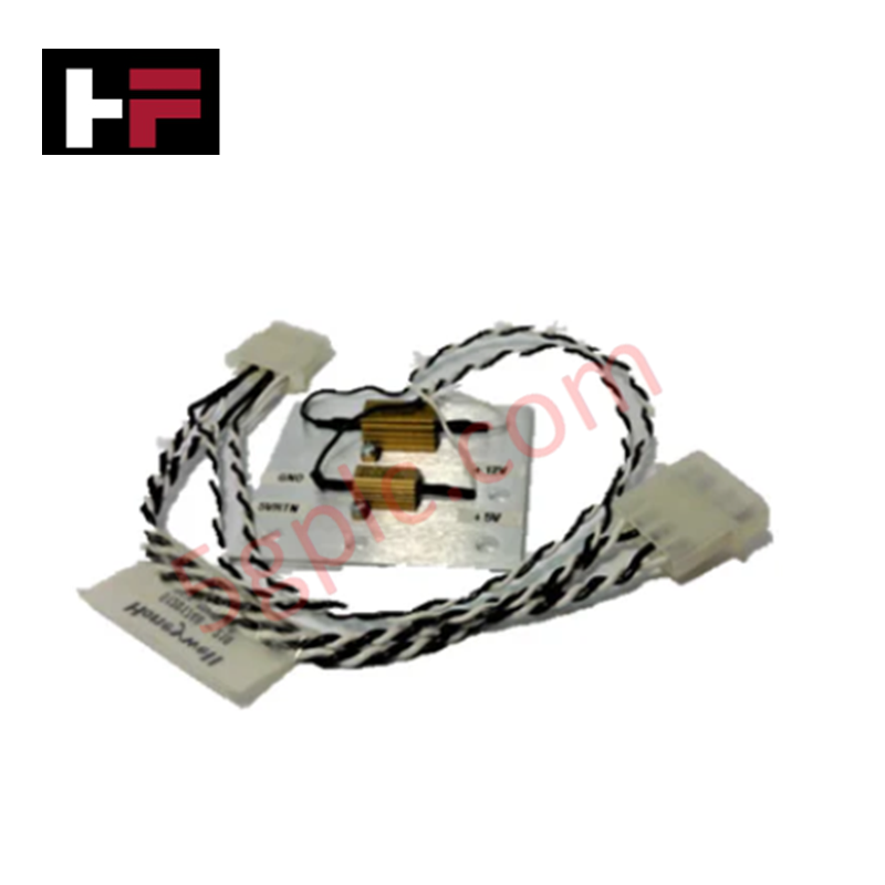
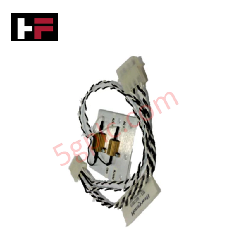
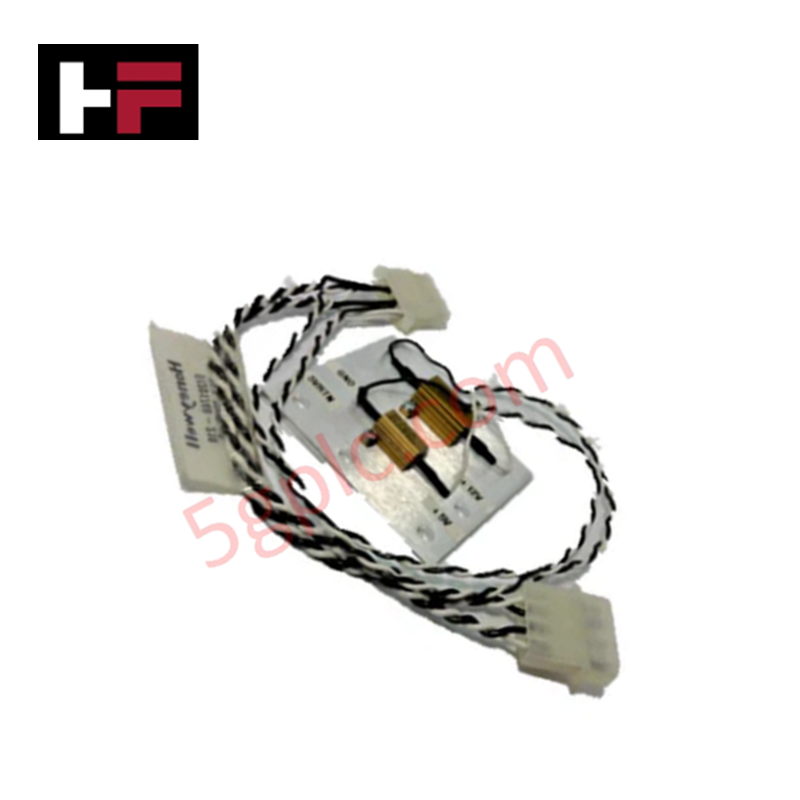
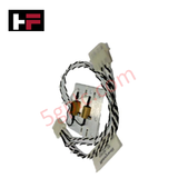
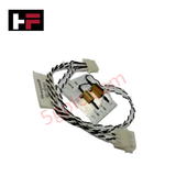
The Honeywell 51201748-210, also cataloged as the 51201748-210 Power Supply Load Resistor Kit, operates as a dedicated hardware component for power supply load simulation and diagnostic loop verification within Honeywell Series C and Experion PKS system enclosures.
Hardware Specifications
| Parameter | Specification |
|---|---|
| Model | 51201748-210 |
| Brand | Honeywell |
| Origin | USA / Global Manufacturing |
| Weight | 0.60 kg (1.32 lbs) |
| Operating Temp | 0 to 60 deg C |
| Power Consumption | Passive Load Element |
| Component Category | Power Components |
| Subcategory | Resistor Kit / Dummy Load Assembly |
| Application | Peripheral power supply load simulation and troubleshooting |
| Mounting Type | Terminal Block / Power Bus Attachment |
| System Compatibility | Honeywell Process Power Supply Modules |
Channel-to-Channel Isolation and Loop Power Simulation
The 51201748-210 load resistor assembly provides a minimum baseline current draw on power supply rails during maintenance and loop staging. In architectures featuring 4-20 mA HART loop protocol field wiring and multi-channel analog modules, power distribution units require minimum current threshold loads to maintain regulated DC output voltages.
Connecting the resistive load element across the bus channels stabilizes system regulation, protecting sensitive channel-to-channel isolation circuits from overvoltage transients during open-circuit test conditions.
Frequently Asked Questions
Q: What primary technical function does the 51201748-210 load resistor serve?
A: The kit simulates active field load conditions on Honeywell system power supplies to enable functional bench testing and diagnostic fault isolation without connected I/O hardware.
Q: Can the 51201748-210 assembly remain connected continuously in a live control panel?
A: It is primarily utilized during commissioning and maintenance; continuous integration depends on power supply minimum load specifications and panel heat dissipation budgets.
Q: How is the assembly physically integrated into the system power rail?
A: The module attaches directly across designated output power terminal blocks or backplane distribution busses using standard screw connection terminals.
Field Installation Guidelines
- Ensure power supply outputs are de-energized prior to installing or removing the 51201748-210 resistor assembly to prevent electrical arcing.
- Maintain adequate clearance around the resistive body to allow convective heat dissipation under energization.
- Verify screw-terminal connections are torqued according to panel specifications to maintain low-resistance electrical contact.
- Route adjacent low-voltage sensor and communication wiring away from thermal dissipation paths created by passive load resistors.
Additional Information
- 100% Genuine Parts: All products are original and authentic, ensuring reliable industrial performance.
- 30-Day Refund Guarantee: Return any in-stock item within 30 days in original, unopened packaging for a full refund (excluding shipping and fees).
- 12-Month Warranty: Covers defects in materials or workmanship; excludes misuse, normal wear, or unauthorized modifications.
- Worldwide Shipping: We ship via USPS, UPS, FedEx, and DHL. Delivery times vary by country and may be subject to customs or import fees.
- Support & Contact: Technical and warranty assistance is available anytime. Contact us here: Contact.
- Purchase Guidance: Check product specifications and compatibility carefully before ordering to ensure proper application.


Tech & Buying Guide

Navigating Industrial Automation Failures: Types, Causes, and Mitigation Strategies
Modern manufacturing relies heavily on automated control systems to maximize throughput and maintain product quality. However, unplanned downtime in industrial automation can cost facility operators thousands of dollars per hour. Understanding how programmable logic controllers (PLCs), distributed control systems (DCS), and field instrumentation fail empowers engineering teams to implement robust preventive maintenance strategies.

Essential Motion Control Commands: A Practical Guide for Engineers
Automation engineers often rely on precise position and speed control to drive modern factory machinery. Modern industrial systems, such as Programmable Logic Controllers (PLCs) and Distributed Control Systems (DCS), depend heavily on standardized motion instructions. Mastering these commands ensures operational safety, protects mechanical components, and optimizes cycle times across production lines.

The Role of Intrinsic Safety Barriers in PLC and DCS Architectures
Implementing robust protection in hazardous industrial environments represents a fundamental safety requirement in factory automation. Process facilities often handle volatile gases, dusts, and chemical agents that pose significant combustion risks. Consequently, control system engineers must deploy energy-limiting interfaces to isolate safe-area control cabinets from hazardous-area field instrumentation. This article examines the function, selection, and electrical principles of intrinsic safety barriers within modern PLC and DCS networks.