










Product Details
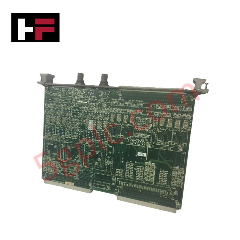
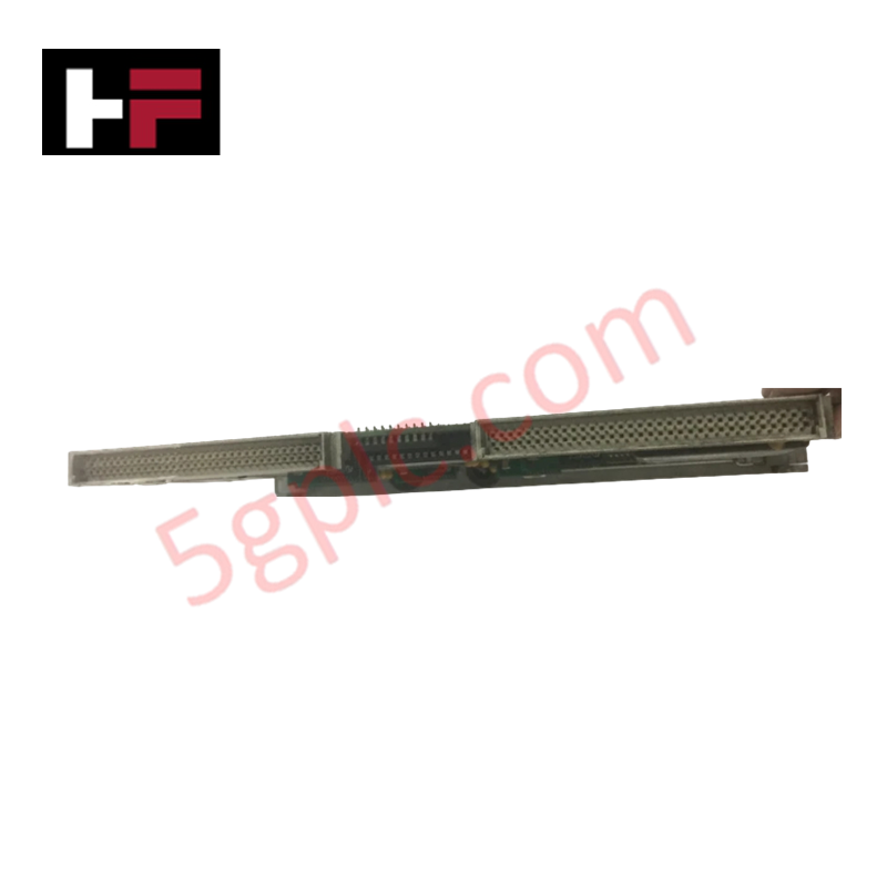
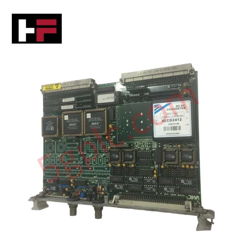
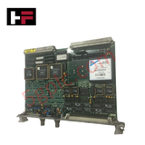
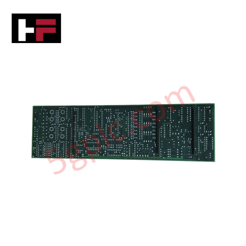
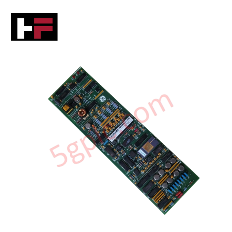
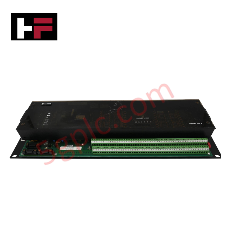
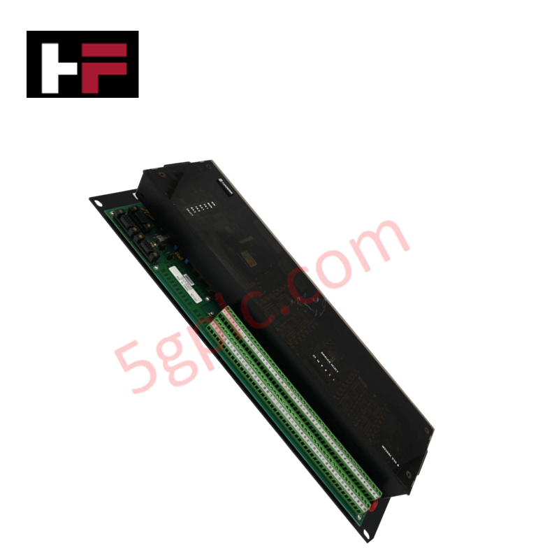
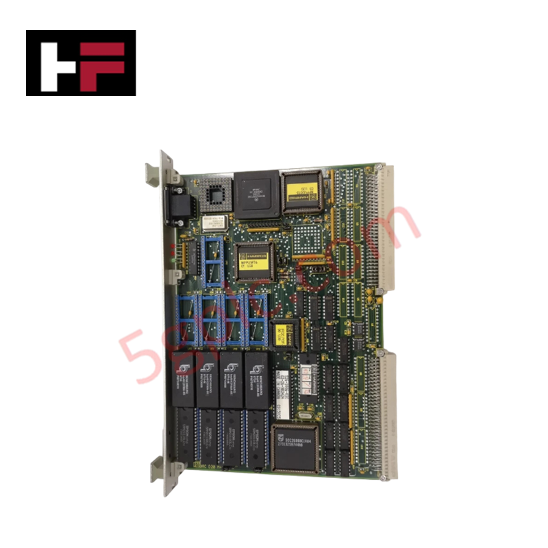
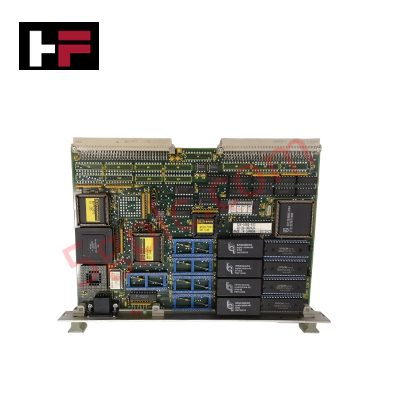
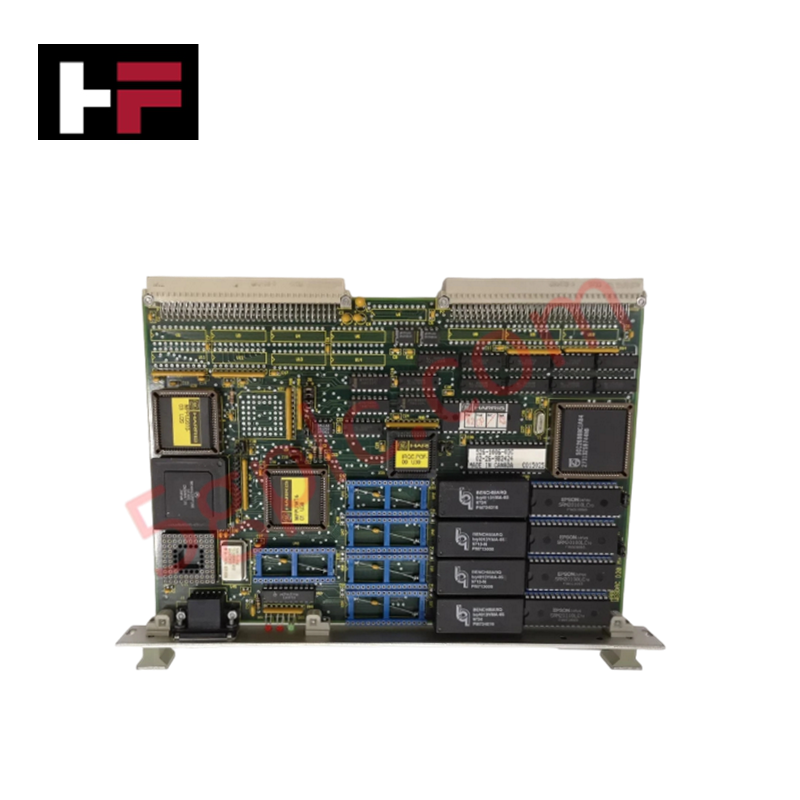
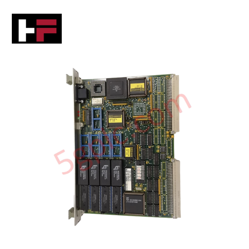
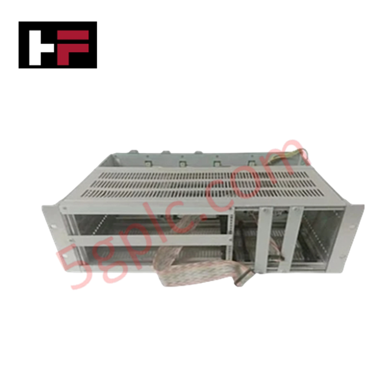
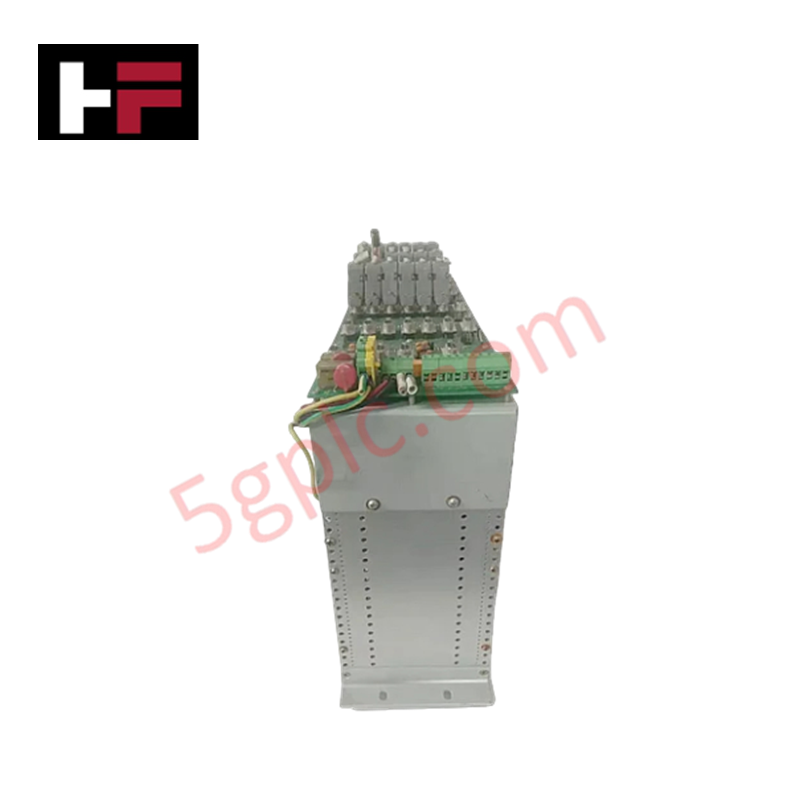
Configured for digital-to-analog signal conversion in industrial automation frameworks, the GE VMIVME-4140 (VMIVME-4140 Analog Output Board) provides direct physical/electrical execution.
Hardware Specifications
| Parameter | Specification |
|---|---|
| Model | VMIVME-4140 |
| Brand | GE Fanuc Automation |
| Origin | United States |
| Weight | Up to 0.7 kg maximum |
| Dimensions | 6U Single-Slot Eurocard Form Factor |
| Operating Temp | 0 - 65 deg C |
| Power Consumption | +5 VDC at 4.0 A maximum (outputs fully loaded) |
| Channel Count | 32 analog output channels |
| Resolution | 12-bit per channel |
| Drive Capability | Sinks or sources 10 mA at +/-10 V |
| Output Impedance | 0.8 ohm |
| Calibration | Automatic calibration via reset or software command |
| Diagnostic Interface | Front panel status LED and reference voltage access |
I/O Density Scaling and Synchronous Register Execution
The board features 32 independent channels, each governed by an assigned Digital-to-Analog Converter (DAC) to preserve strict channel isolation and mitigate signal degradation. To support dense I/O density scaling without scanning latency, the architecture processes random updates natively. Double-buffered outputs allow the system to execute software-driven or external synchronous updates, locking the voltage profiles across all 32 channels simultaneously to preserve deterministic loop execution.
Frequently Asked Questions
Q: Does the VMIVME-4140 support live insertion or hot-swapping during operation?
A: No. The standard VMEbus 6U architecture utilized by this board lacks live-insertion pin sequencing. Attempting to hot-swap the module while the +5 VDC rail is energized can generate bus transients, causing data corruption or damage to the internal DAC array.
Q: How can output channels be verified without affecting the physical field actuators?
A: The board features extensive onboard diagnostic testing capabilities. Operators can use software commands to disconnect the analog outputs from the field terminal paths, allowing comprehensive offline loop self-testing.
Field Installation Guidelines
- Mechanical Mounting: Insert the single-slot card into the designated 6U VME chassis guides. Ensure the injector/ejector handles lock fully into place to seat the backplane pins correctly before fastening the faceplate screws.
- Termination Options: Field connections must be wired using either discrete point-to-point conductors or an IDC mass-terminal connector block attached directly to the front panel receptacle.
- Noise Mitigation: Maintain isolation between low-impedance analog paths and high-voltage AC lines. All signal wires must use shielded twisted-pair configurations grounded at the cabinet entry barrier to protect the 12-bit outputs from industrial EMI.
Additional Information
- 100% Genuine Parts: All products are original and authentic, ensuring reliable industrial performance.
- 30-Day Refund Guarantee: Return any in-stock item within 30 days in original, unopened packaging for a full refund (excluding shipping and fees).
- 12-Month Warranty: Covers defects in materials or workmanship; excludes misuse, normal wear, or unauthorized modifications.
- Worldwide Shipping: We ship via USPS, UPS, FedEx, and DHL. Delivery times vary by country and may be subject to customs or import fees.
- Support & Contact: Technical and warranty assistance is available anytime. Contact us here: Contact.
- Purchase Guidance: Check product specifications and compatibility carefully before ordering to ensure proper application.
Tech & Buying Guide

Executing a PLC System Site Acceptance Test (SAT): The Definitive Engineering Guide
The transition of a Programmable Logic Controller (PLC) cabinet from a controlled factory floor to a volatile plant environment represents a critical milestone in factory automation. While a Factory Acceptance Test (FAT) validates standalone hardware compliance under ideal conditions, it cannot replicate real-world process dynamics. Therefore, deploying an industrial automation system requires a rigorous Site Acceptance Test (SAT) to verify total loop integrity, field wiring wiring metrics, and process control parameters before final customer handover.

Advanced Integration: Master Protocol for VFD Commissioning and Testing
Deploying variable frequency drives (VFDs) requires precise execution during the initial commissioning phase. Junior automation engineers often find the first power-up sequence intimidating. However, following a rigorous engineering framework ensures equipment safety and system reliability. Proper startup procedures protect both the drive electronics and the connected motor.

Optimizing Factory Automation: The Definitive Guide to VFD Preventive Maintenance
Variable Frequency Drives (VFDs) serve as critical assets in modern industrial automation. These power electronic devices regulate electric motors by adjusting the supplied frequency and voltage. Consequently, industries utilize VFDs to reduce energy consumption and optimize process control. Major manufacturers like Siemens, ABB, and Yaskawa design highly efficient drives. However, sustained efficiency requires a rigorous preventive maintenance program.