










Product Details
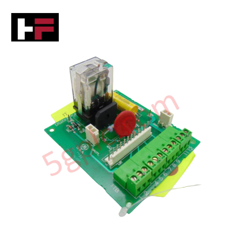
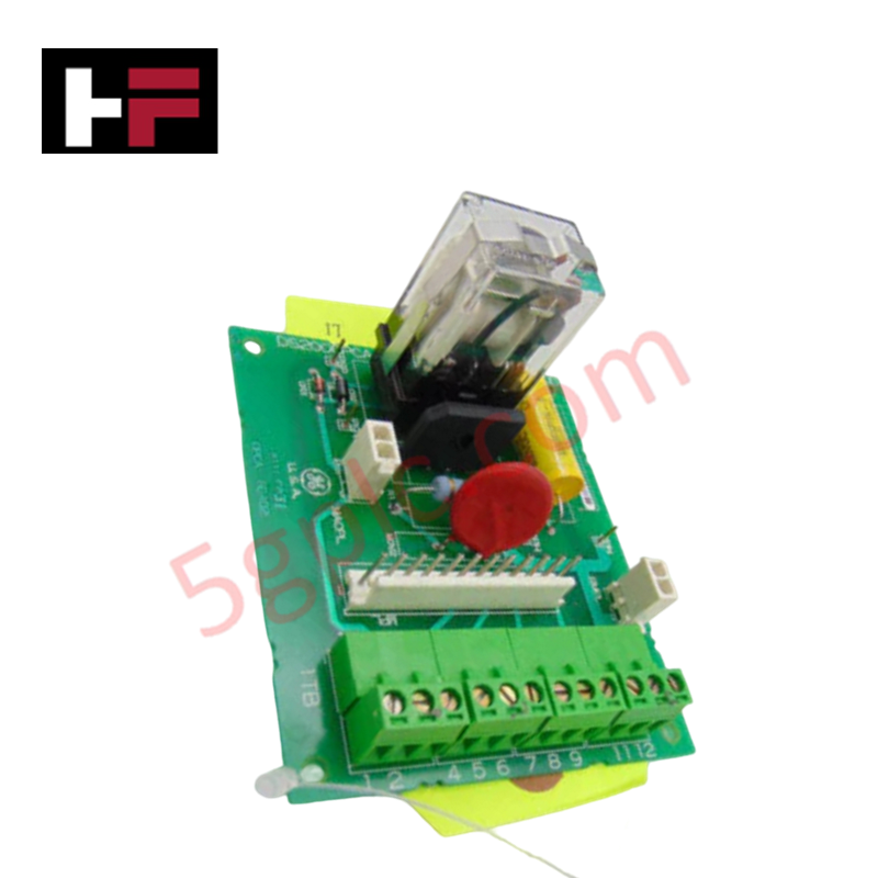
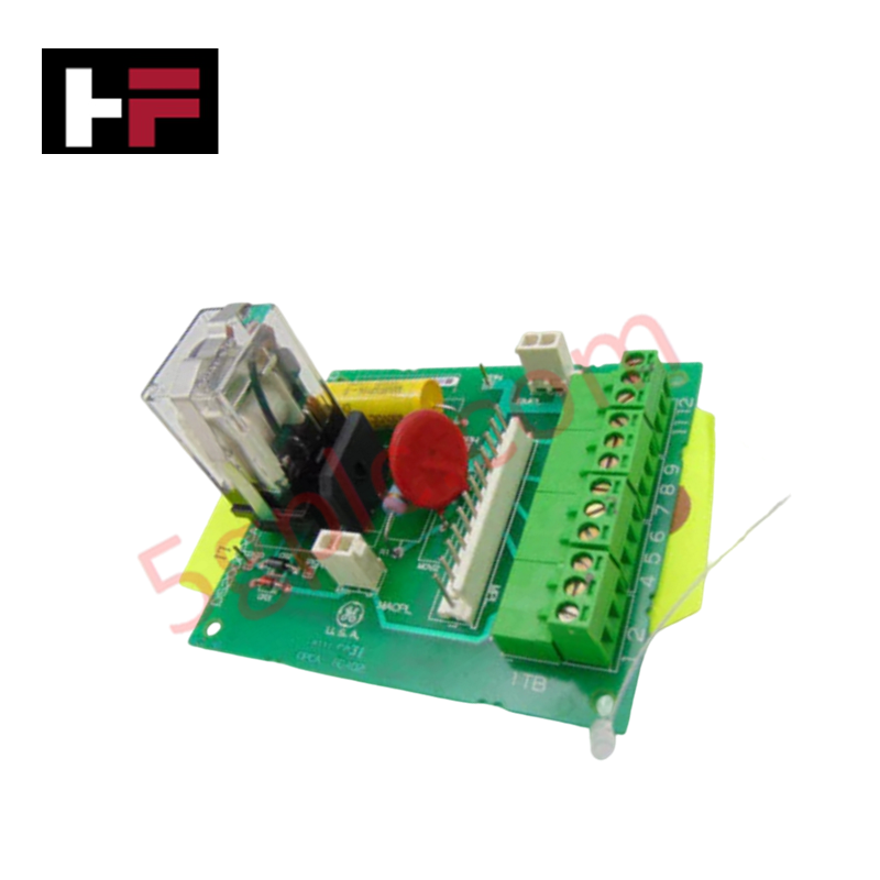
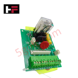
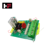
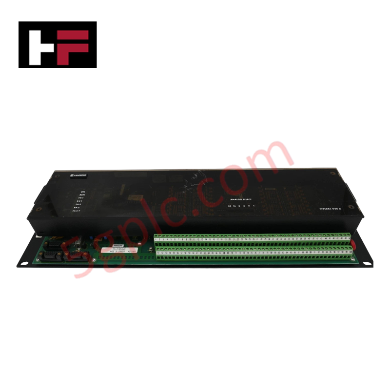
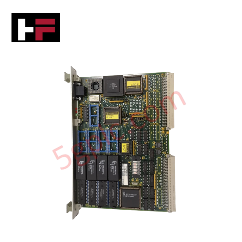
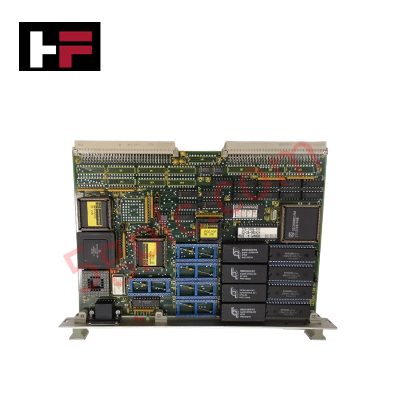
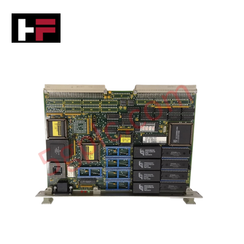
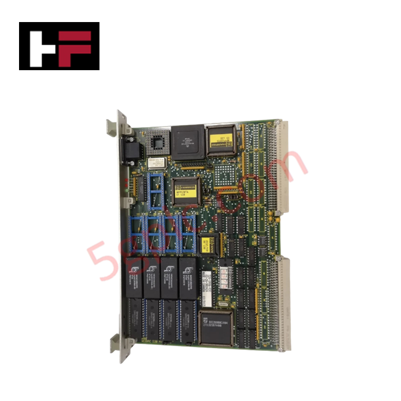
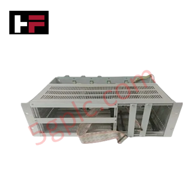
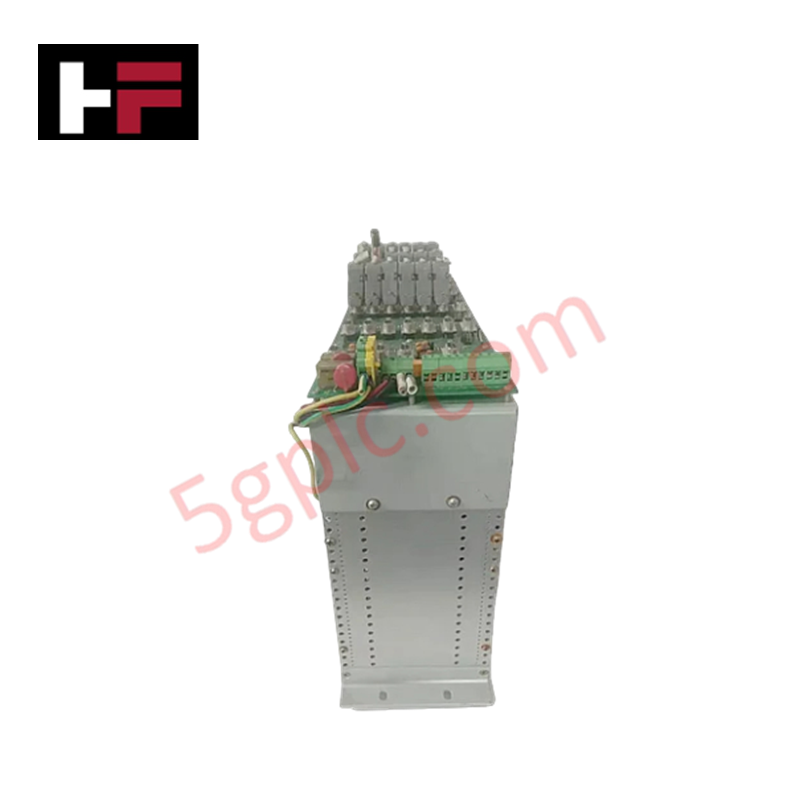
Configured for contactor control and excitation management in EX2000 systems, the GE DS200CPCAG1A (DS200CPCA Contactor Pilot Board) provides direct physical/electrical execution of coil switching sequences.
Hardware Specifications
| Parameter | Specification |
|---|---|
| Model | DS200CPCAG1A |
| Brand | GE (General Electric) |
| Origin | USA |
| Weight | 0.45 kg |
| Dimensions | 23.8 cm x 8.6 cm |
| Operating Temp | -35 to 65 deg C |
| Power Consumption | 25 VDC (Control Logic) |
| Input Voltage | 115 VAC |
| Output Voltage | 105 VDC (Contactor Coil Drive) |
PLC/DCS Deterministic Network Integration
The DS200CPCAG1A manages contactor state transitions by rectifying 115 VAC input into 105 VDC output for coil actuation. Integration into the EX2000 system requires precise coordination with the existing backplane bus communication velocity. As a critical link in the excitation sequence, this board maintains deterministic timing during state changes, ensuring that coil voltage is sustained to keep the contactor closed. Firmware flash compatibility and hardware handshaking protocols must be verified against the host controller revision to prevent timing latencies during high-frequency switching operations.
Frequently Asked Questions
Q: Can the test points CPH and CPN be measured with standard grounded multimeters?
A: No. CPH and CPN are not referenced to the drive's common level. All measurements must be performed using isolated test equipment capable of measuring floating potentials to prevent circuit damage or ground fault conditions.
Q: How does the CPCA functionality differ from the CDBA board in terms of load handling?
A: While the CDBA board initiates the electricity for contactor operation, the CPCA board provides the full voltage required to close and maintain the contactor in a closed state, assuming the primary load responsibilities for the coil drive.
Field Installation Guidelines
- Mounting: Ensure the board is securely seated in the designated EX2000 cabinet slot using the provided guide rails. Verify mechanical clearance for the 23.8 cm x 8.6 cm footprint.
- Wiring: Use appropriate gauge wire for the 115 VAC input connections. Ensure all terminals are tightened to specified torque values to prevent high-resistance connections and overheating during continuous coil activation.
- Grounding and Shielding: Ensure the cabinet chassis is properly earth-grounded. Because the board handles AC-to-DC conversion for inductive loads, maintain physical separation between signal cables and high-power conductors to mitigate electromagnetic interference.
- Testing: Before applying full system power, perform continuity checks using isolated equipment at the designated test points (CPH, CPN, PSP, PSN) to verify correct voltage polarity and conversion levels.
Additional Information
- 100% Genuine Parts: All products are original and authentic, ensuring reliable industrial performance.
- 30-Day Refund Guarantee: Return any in-stock item within 30 days in original, unopened packaging for a full refund (excluding shipping and fees).
- 12-Month Warranty: Covers defects in materials or workmanship; excludes misuse, normal wear, or unauthorized modifications.
- Worldwide Shipping: We ship via USPS, UPS, FedEx, and DHL. Delivery times vary by country and may be subject to customs or import fees.
- Support & Contact: Technical and warranty assistance is available anytime. Contact us here: Contact.
- Purchase Guidance: Check product specifications and compatibility carefully before ordering to ensure proper application.
Tech & Buying Guide

Executing a PLC System Site Acceptance Test (SAT): The Definitive Engineering Guide
The transition of a Programmable Logic Controller (PLC) cabinet from a controlled factory floor to a volatile plant environment represents a critical milestone in factory automation. While a Factory Acceptance Test (FAT) validates standalone hardware compliance under ideal conditions, it cannot replicate real-world process dynamics. Therefore, deploying an industrial automation system requires a rigorous Site Acceptance Test (SAT) to verify total loop integrity, field wiring wiring metrics, and process control parameters before final customer handover.

Advanced Integration: Master Protocol for VFD Commissioning and Testing
Deploying variable frequency drives (VFDs) requires precise execution during the initial commissioning phase. Junior automation engineers often find the first power-up sequence intimidating. However, following a rigorous engineering framework ensures equipment safety and system reliability. Proper startup procedures protect both the drive electronics and the connected motor.

Optimizing Factory Automation: The Definitive Guide to VFD Preventive Maintenance
Variable Frequency Drives (VFDs) serve as critical assets in modern industrial automation. These power electronic devices regulate electric motors by adjusting the supplied frequency and voltage. Consequently, industries utilize VFDs to reduce energy consumption and optimize process control. Major manufacturers like Siemens, ABB, and Yaskawa design highly efficient drives. However, sustained efficiency requires a rigorous preventive maintenance program.