










Product Details
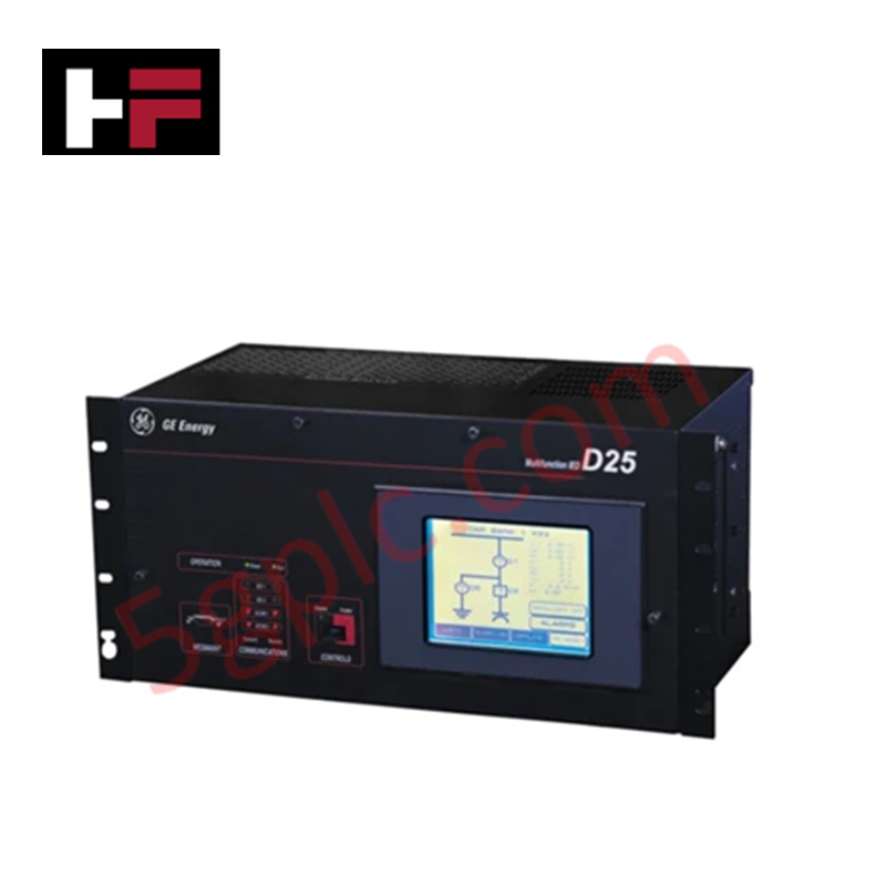
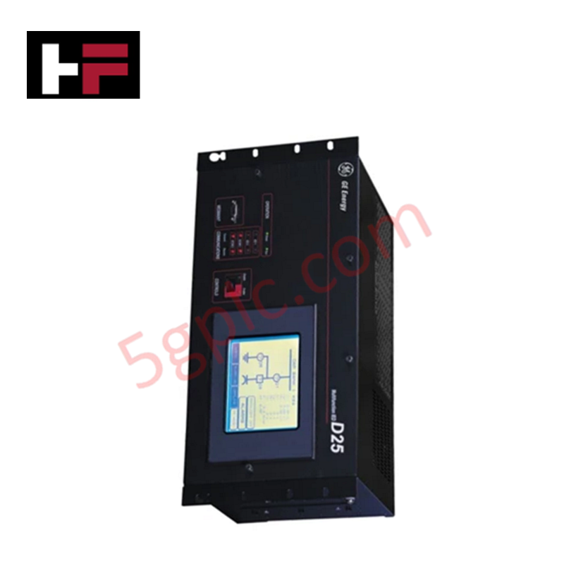
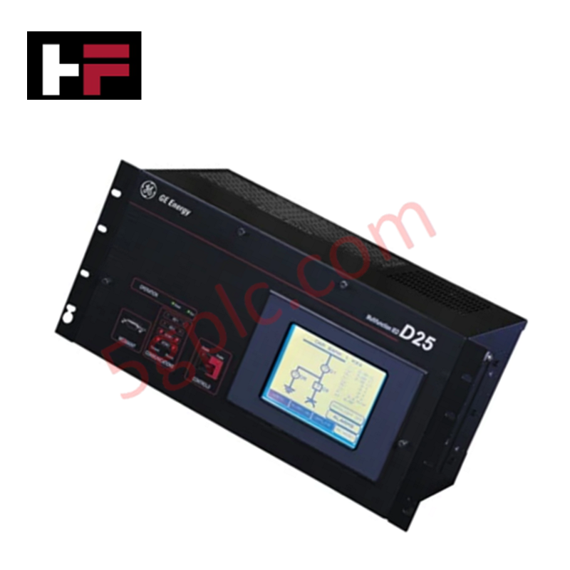
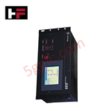
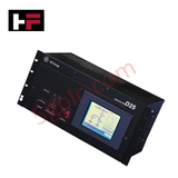
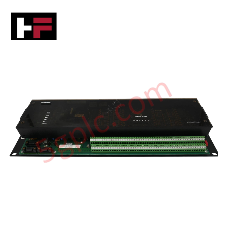
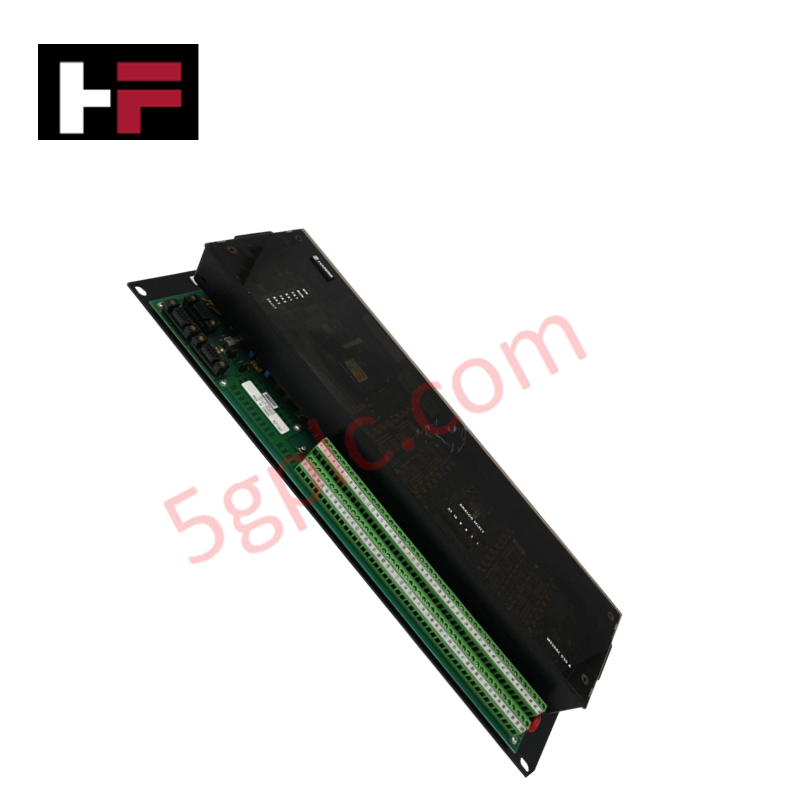
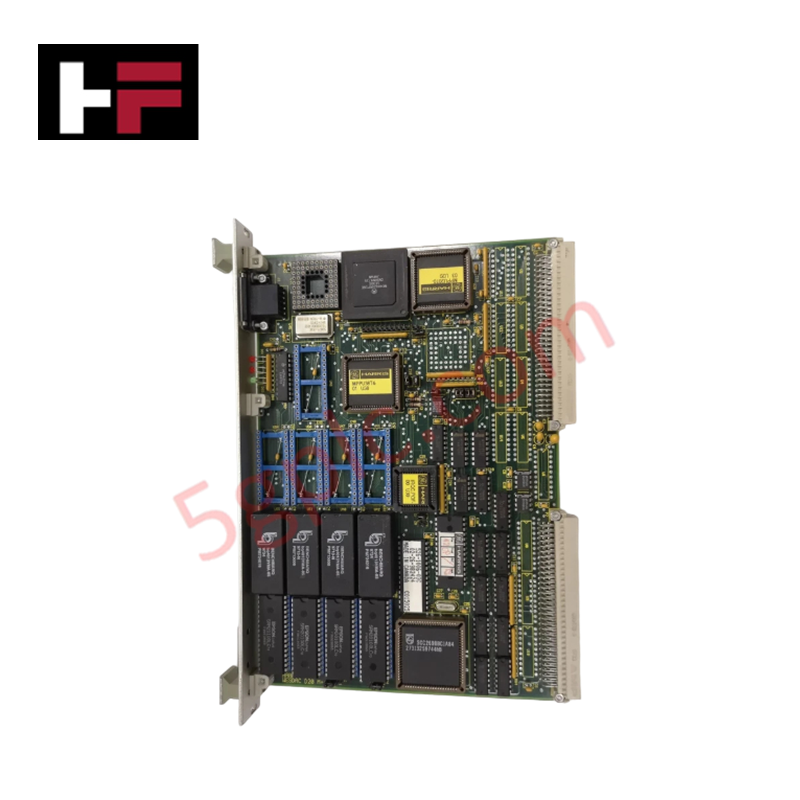
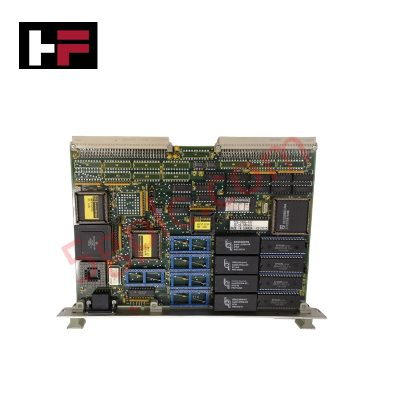
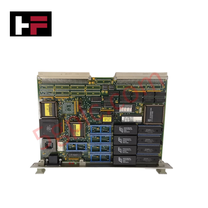
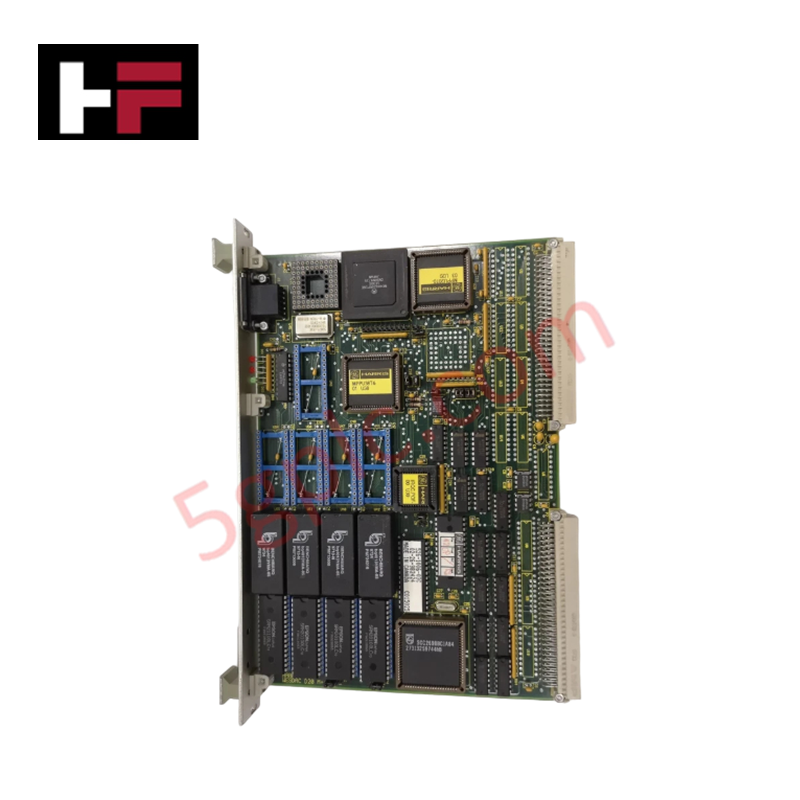
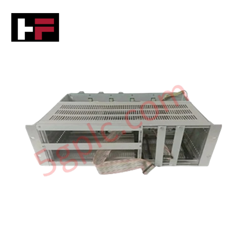
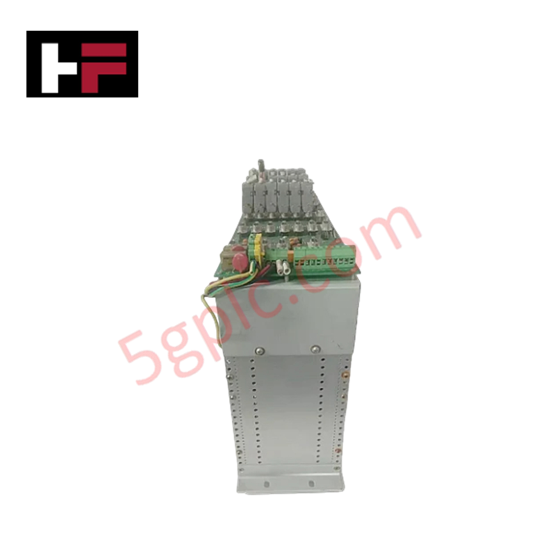
Configured for high-speed electrical parameters logging and substation automation control, the GE Fanuc D25-0158-000003 (D25 Industrial Controller) provides direct physical/electrical execution. The hardware acquires multi-channel waveforms from 15 transformer-isolated AC analog inputs to run specialized calculations up to six-phase circuits. Communication routines run via independent physical serial and optional Ethernet ports, balancing processing resources across embedded measuring matrices and remote telecontrol pipelines.
Hardware Specifications
| Parameter | Specification |
|---|---|
| Model | D25-0158-000003 |
| Brand | GE Fanuc |
| Origin | Technical specifications determine factory origin |
| Weight | Internal chassis option dependent |
| Dimensions | Standard D25 form factor requirements apply |
| Operating Temp | Industrial grade classification |
| Power Consumption | Base unit draw plus communication card configuration loads |
| AC Analog Inputs | 15 channels (grouped in triads, transformer isolated) |
| Sampling Performance | 64 samples per Power Line Cycle |
| A/D Resolution | 13 bits plus sign |
| PT Input Selections | 63.5 Vrms, 69.3 Vrms, 110 Vrms, 120 Vrms, 220 Vrms nominal |
| Measurement Limits | 0% to 250% of nominal baseline |
| Overload Tolerances | 250% nominal continuous, 350% nominal for 60 seconds |
| Input Burden Value | Less than 0.1 VA at nominal voltage input |
| System Accuracy | Voltage: +/-0.5% of nominal, Frequency: +/-0.01 Hz, Phase Angle: +/-0.5 deg |
| Local Interfaces | WESMAINT II+ DB-9-F (RS-232 @ 9600 bps), Display Port (RS-485 @ 9600 bps) |
| System Time Sync | UTC Time Port (DB-9-F, RS-232/RS-422) |
| Serial Links | DB-9-F standard and optional ports (RS-232/485 up to 38400 bps) |
| Ethernet Expansion | Optional 10/100TX, 10FL, or 100FX configurations |
Profinet / EtherNet/IP Deterministic Networks Integration
The processing architecture organizes discrete data partitions to execute simultaneous 64-sample-per-cycle A/D routines without compromising the deterministic bandwidth of the communication buses. The firmware ensures absolute flash compatibility across the variable interface ports, keeping protocol parsing routines on the optional 10/100TX or 100FX Ethernet cards isolated from the primary 13-bit conversion pipeline. This internal isolation prevents serial polling peaks or timing requests at the UTC interface from degrading the accuracy calculations of the six-phase power line matrices.
Frequently Asked Questions
Q: How is firmware flash compatibility managed when swapping optional Ethernet interfaces on the D25 platform?
A: During hardware initialization, the core processor executes an option-slot verification sequence. The installed hardware version must align with the loaded system image constraints; mismatched firmware parameters will inhibit bus execution and stop communication initialization.
Q: Can the 15 AC analog input connections be serviced or hot-swapped while primary instrument lines are energized?
A: No. The backplane and terminal blocks do not feature open-circuit protection for active transformer lines. The PT and CT secondary paths must be short-circuited or isolated before disconnecting any terminal blocks to avoid electrical damage or dangerous transient voltages.
Field Installation Guidelines
- Earthing Framework: Ground the controller frame by running a low-impedance copper cable from the grounding terminal on the chassis directly to the master control panel earth grid.
- Analog Line Layout: Route the 15 instrument-isolated AC analog lines through grounded steel conduits to prevent electromagnetic fields from causing errors in the phase angle and frequency metrics.
- Fiber Optic Routing: When using the optional 10FL or 100FX optical cards, enforce the minimum bend radius guidelines inside the wiring trays to avoid physical fiber fractures or excessive signal loss.
Additional Information
- 100% Genuine Parts: All products are original and authentic, ensuring reliable industrial performance.
- 30-Day Refund Guarantee: Return any in-stock item within 30 days in original, unopened packaging for a full refund (excluding shipping and fees).
- 12-Month Warranty: Covers defects in materials or workmanship; excludes misuse, normal wear, or unauthorized modifications.
- Worldwide Shipping: We ship via USPS, UPS, FedEx, and DHL. Delivery times vary by country and may be subject to customs or import fees.
- Support & Contact: Technical and warranty assistance is available anytime. Contact us here: Contact.
- Purchase Guidance: Check product specifications and compatibility carefully before ordering to ensure proper application.
Tech & Buying Guide
Executing a PLC System Site Acceptance Test (SAT): The Definitive Engineering Guide
The transition of a Programmable Logic Controller (PLC) cabinet from a controlled factory floor to a volatile plant environment represents a critical milestone in factory automation. While a Factory Acceptance Test (FAT) validates standalone hardware compliance under ideal conditions, it cannot replicate real-world process dynamics. Therefore, deploying an industrial automation system requires a rigorous Site Acceptance Test (SAT) to verify total loop integrity, field wiring wiring metrics, and process control parameters before final customer handover.

Advanced Integration: Master Protocol for VFD Commissioning and Testing
Deploying variable frequency drives (VFDs) requires precise execution during the initial commissioning phase. Junior automation engineers often find the first power-up sequence intimidating. However, following a rigorous engineering framework ensures equipment safety and system reliability. Proper startup procedures protect both the drive electronics and the connected motor.

Optimizing Factory Automation: The Definitive Guide to VFD Preventive Maintenance
Variable Frequency Drives (VFDs) serve as critical assets in modern industrial automation. These power electronic devices regulate electric motors by adjusting the supplied frequency and voltage. Consequently, industries utilize VFDs to reduce energy consumption and optimize process control. Major manufacturers like Siemens, ABB, and Yaskawa design highly efficient drives. However, sustained efficiency requires a rigorous preventive maintenance program.