










Product Details
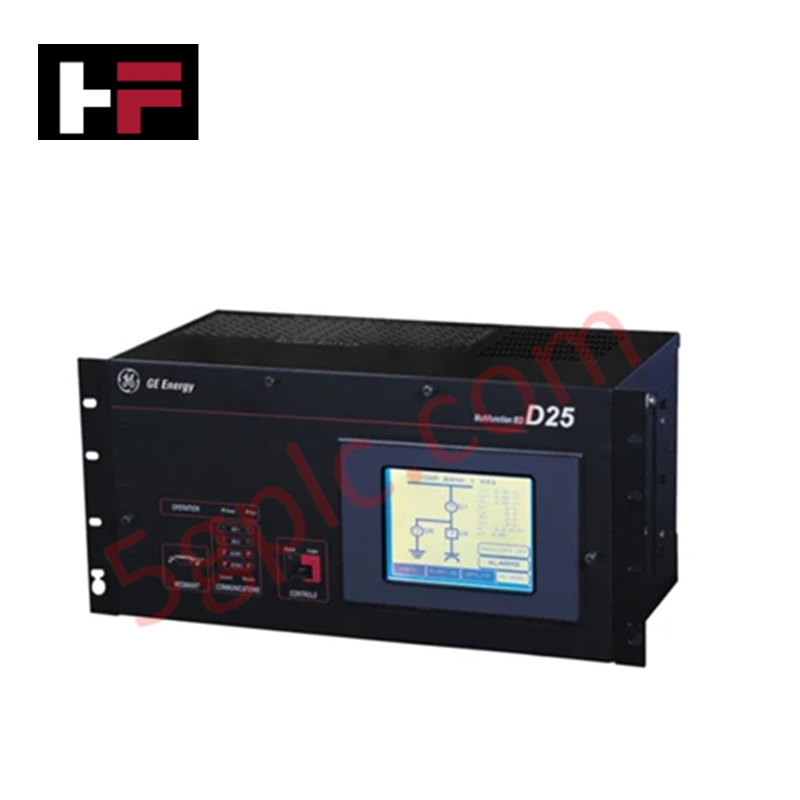
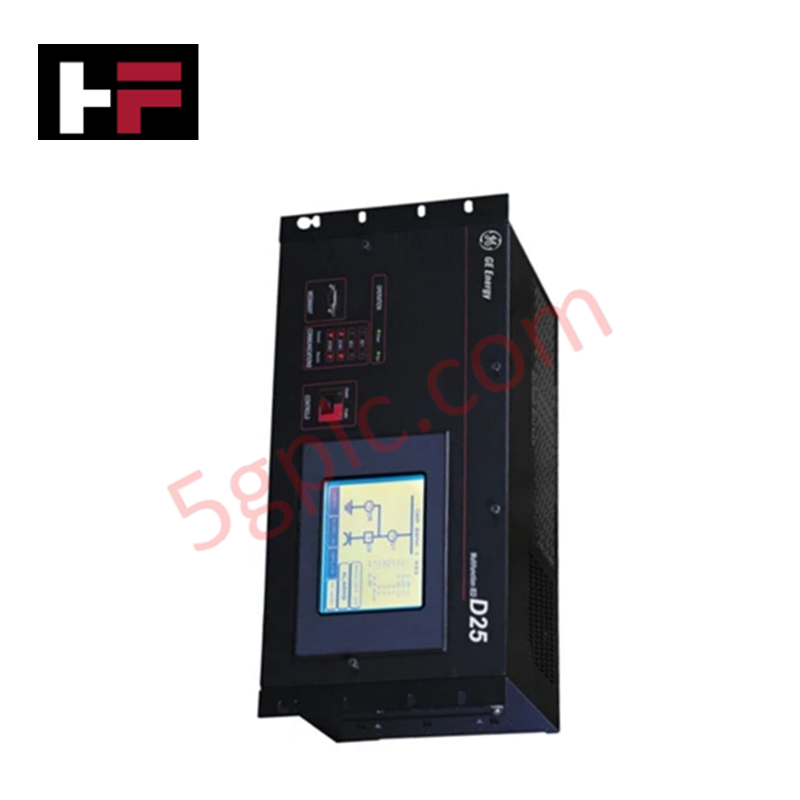
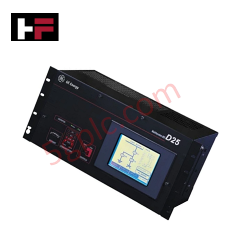
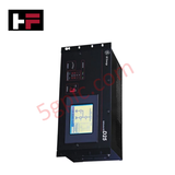
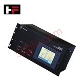
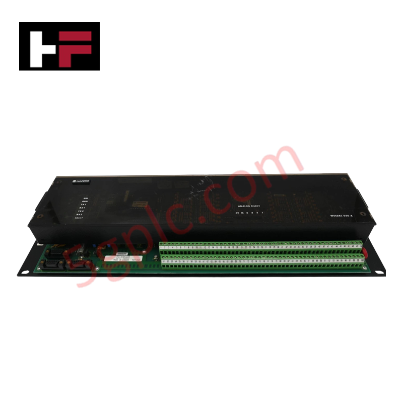
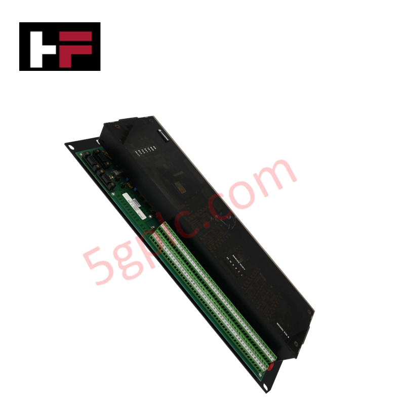
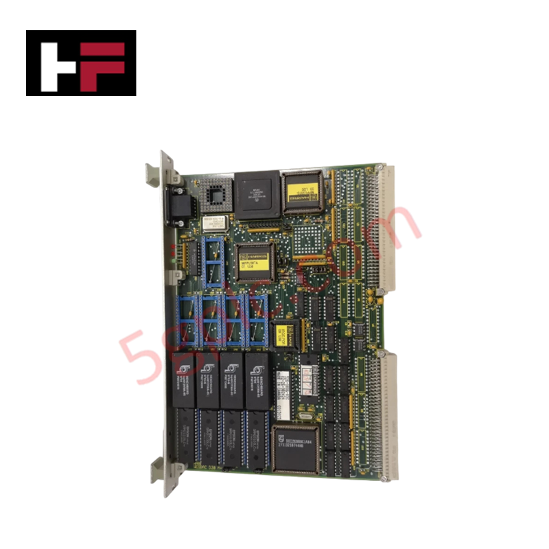
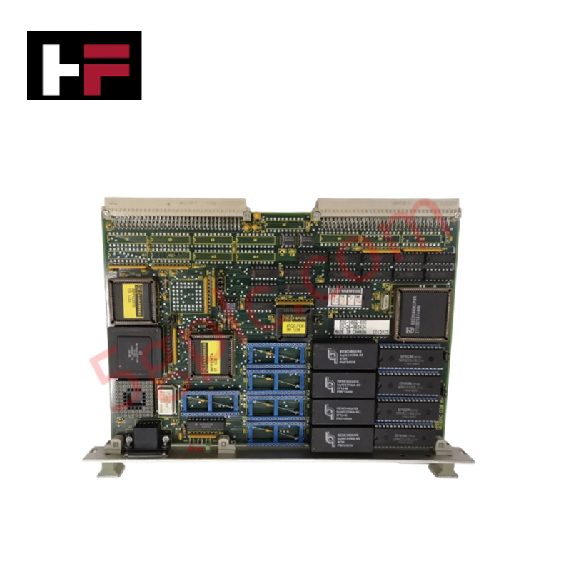
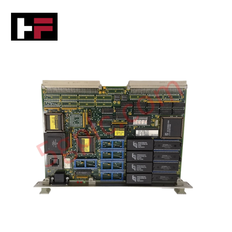
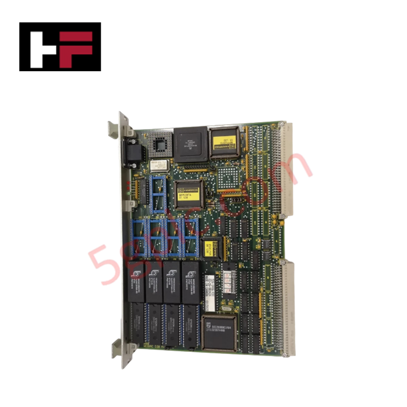
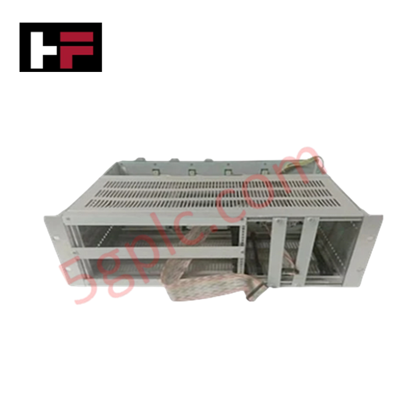
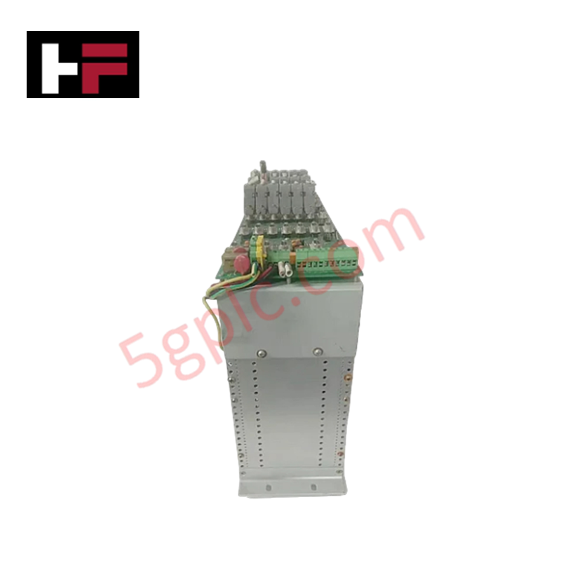
The GE Fanuc D25-0158-000001 serves as the primary D25 Digital I/O Module utilized to execute digital telemetry monitoring and contact output operations across industrial automation platforms. The hardware processes up to 96 optically isolated bipolar digital inputs grouped in 32-channel matrices, enabling precise Sequence of Events (SOE) tracking with 1 ms time-tagging. Concurrently, it drives downstream field devices through up to 32 relay outputs featuring select-check-before-execute software verification and single-component failure detection.
Hardware Specifications
| Parameter | Specification |
|---|---|
| Model | D25-0158-000001 |
| Brand | GE Fanuc |
| Origin | Technical specifications determine factory origin |
| Weight | Internal hardware card configuration dependent |
| Dimensions | Standard D25 series rack envelope compatibility |
| Operating Temp | Industrial grade environmental tolerance |
| Power Consumption | Determined by total active I/O count and loop wetting |
| Optical Isolation (Inputs) | 5000 Vrms |
| Input Voltage Ratings | 125 Vdc / 250 V Vdc options / Tolerances: +/-20%, bipolar |
| Input Current Burden | 1.2 to 10 mA / Maximum power dissipation 0.5 W per input |
| Time-Tagging Accuracy | 1 ms resolution for Sequence of Events (SOE) data |
| Wetting Source | On-board wetting voltage provision integrated |
| Relay Configurations | 16 or 32 relay channels / 1 Form A contact type |
| Output Switching Limits | Maximum 60 W or 125 VA (resistive load) |
| Output Voltages | 75 Vdc or 50 Vac (DB-25), 120 Vdc (FACE-40) maximum |
| Output Current Ratings | 2 A maximum switching / 2 A maximum carrying |
| Relay Timing Profiles | Operate time: 5 ms / Release time: 5 ms |
| Output Isolation Limits | 1500 Vac for 1 minute (coil-to-contact); Inter-output: 300 Vdc (compression terminal block) or 100 Vdc (DB-25) |
Profinet / EtherNet/IP Deterministic Networks Integration
The module processor maintains internal register synchronization over the system backplane, ensuring absolute firmware flash compatibility when mapping high-density input channels. The hardware separates localized A/D and digital state sampling from host network polling routines, allowing the three-level software filtering engine to suppress contact chatter without modifying the deterministic processing of the core logic. Pulse accumulator loops on up to 8 designated inputs scale independently from communication port traffic, preventing packet dropouts from affecting totals.
Frequently Asked Questions
Q: Can the D25-0158-000001 module cards be hot-swapped while the 120 Vdc or 250 Vdc wetting voltages are active on the field terminals?
A: No. The internal backplane pins and signal traces do not feature live isolation barriers. All auxiliary and field power loops must be fully de-energized prior to removing or inserting modules to prevent transient voltage arcing or damage to the optical isolators.
Q: How is the select-check-before-execute security handled if a single component fails inside the output circuitry?
A: The onboard hardware architecture incorporates dual-path validation paths. If an internal component failure occurs within the activation driver, the module detects the diagnostic state mismatch during the "check" phase and blocks the final execution sequence, keeping the 1 Form A contact open.
Field Installation Guidelines
- Chassis Grounding Protection: Connect a low-impedance copper conductor from the chassis ground stud directly to the control cabinet master earth bus bar before connecting field wiring.
- Input Signal Separation: Route all 12 Vdc to 250 Vdc discrete input lines in separate wiring ducts away from high-power AC motor supply lines to reduce inductive noise coupling into the debounce filters.
- Output Isolation Boundaries: When utilizing DB-25 connector configurations, ensure the external voltage across adjacent channels does not exceed the 100 Vdc maximum isolation limit. Use compression terminal blocks if 300 Vdc inter-output isolation is required.
Additional Information
- 100% Genuine Parts: All products are original and authentic, ensuring reliable industrial performance.
- 30-Day Refund Guarantee: Return any in-stock item within 30 days in original, unopened packaging for a full refund (excluding shipping and fees).
- 12-Month Warranty: Covers defects in materials or workmanship; excludes misuse, normal wear, or unauthorized modifications.
- Worldwide Shipping: We ship via USPS, UPS, FedEx, and DHL. Delivery times vary by country and may be subject to customs or import fees.
- Support & Contact: Technical and warranty assistance is available anytime. Contact us here: Contact.
- Purchase Guidance: Check product specifications and compatibility carefully before ordering to ensure proper application.
Tech & Buying Guide

Executing a PLC System Site Acceptance Test (SAT): The Definitive Engineering Guide
The transition of a Programmable Logic Controller (PLC) cabinet from a controlled factory floor to a volatile plant environment represents a critical milestone in factory automation. While a Factory Acceptance Test (FAT) validates standalone hardware compliance under ideal conditions, it cannot replicate real-world process dynamics. Therefore, deploying an industrial automation system requires a rigorous Site Acceptance Test (SAT) to verify total loop integrity, field wiring wiring metrics, and process control parameters before final customer handover.

Advanced Integration: Master Protocol for VFD Commissioning and Testing
Deploying variable frequency drives (VFDs) requires precise execution during the initial commissioning phase. Junior automation engineers often find the first power-up sequence intimidating. However, following a rigorous engineering framework ensures equipment safety and system reliability. Proper startup procedures protect both the drive electronics and the connected motor.

Optimizing Factory Automation: The Definitive Guide to VFD Preventive Maintenance
Variable Frequency Drives (VFDs) serve as critical assets in modern industrial automation. These power electronic devices regulate electric motors by adjusting the supplied frequency and voltage. Consequently, industries utilize VFDs to reduce energy consumption and optimize process control. Major manufacturers like Siemens, ABB, and Yaskawa design highly efficient drives. However, sustained efficiency requires a rigorous preventive maintenance program.